|
"ONSHORE ISO SHIPPING CONTAINERS" VS "OFFSHORE DNV SHIPPING CONTAINERS"
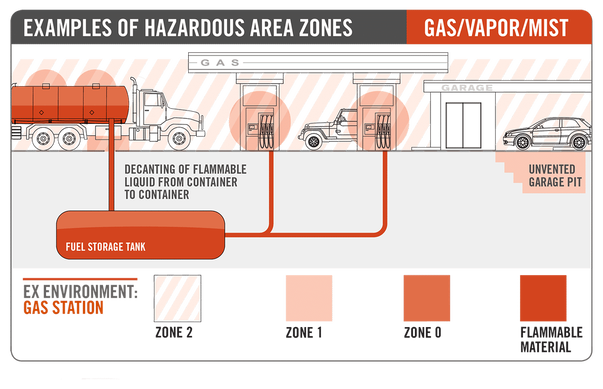
DIFFERENT HAZARDOUS AREAS HAVE A CERTAIN IMPACT ON THE DESIGN OF CONTAINERS, BUT HOW TO IDENTIFY ZONE 0, ZONE 1, AND ZONE 2 HAZARDOUS AREAS?
 ABS guildline for portable offshore accommodation modules The installation of modular buildings for use as living quarters, industrial spaces, and workshops has become increasingly prevalent in recent years. Irrespective of the amount of time that portable modules are installed onboard, the potential risks to personnel within these buildings can be comparable to those within a traditional living quarters structure. Due to the transient nature of portable accommodation modules, it is possible that the buildings may be installed on a number of different types of vessels and offshore units over their life. In recognizing that the ABS class requirements differ based on the type of host vessel or facility, this Guide has been created to outline the process for the design and survey of the modules and to establish the requirements for modules which can be used on any category of offshore drilling unit, production facility, barge, steel vessel, or high speed craft. Class Approval Process The ABS approval process for accommodation modules is a four-step process as outlined below: • Design Review of the Module • Survey of the Module at Fabrication Facility • Design Review for Installation Approval • Survey onboard Host Vessel The ABS review process of the module commences with drawings and documentation detailing the module’s general arrangements, structural fire protection, electrical configuration, structural design, and machinery and piping systems being submitted to the ABS technical office for review. Upon completion of the review, drawings will be returned to the submitter and forwarded to the attending ABS Surveyor. Receipt of the drawings by the ABS Surveyor permits the physical survey of the module at the fabrication facility to be commenced. Once a host vessel for the module is determined, design review for installation approval can be commenced. Upon receipt of the documentation detailing the module and the proposed location onboard the host vessel, the ABS technical office can review the arrangements. Once the ABS engineers have determined that the proposed location onboard the host vessel is suitable for the subject module, stamped drawings will be returned to the submitter and made available to the attending ABS Survey office. Upon receipt of these drawings, the attending ABS Surveyor may attend the vessel and confirm that the installation of the modules is in accordance with the approved arrangements. The manufacturer is to assign a unique serial number to identify all modules being reviewed to this Guide. The initial submission of drawings is to specifically indicate the serial number of modules to be built in accordance with the drawings. Please download TLS accommodation modular brochure , TLS ABS approved offshore accommodation module brochure for reference. More information about accommodation modulars, offshore accommodation cabins, gallery module, mess module, etc. Please contact [email protected] for more information.
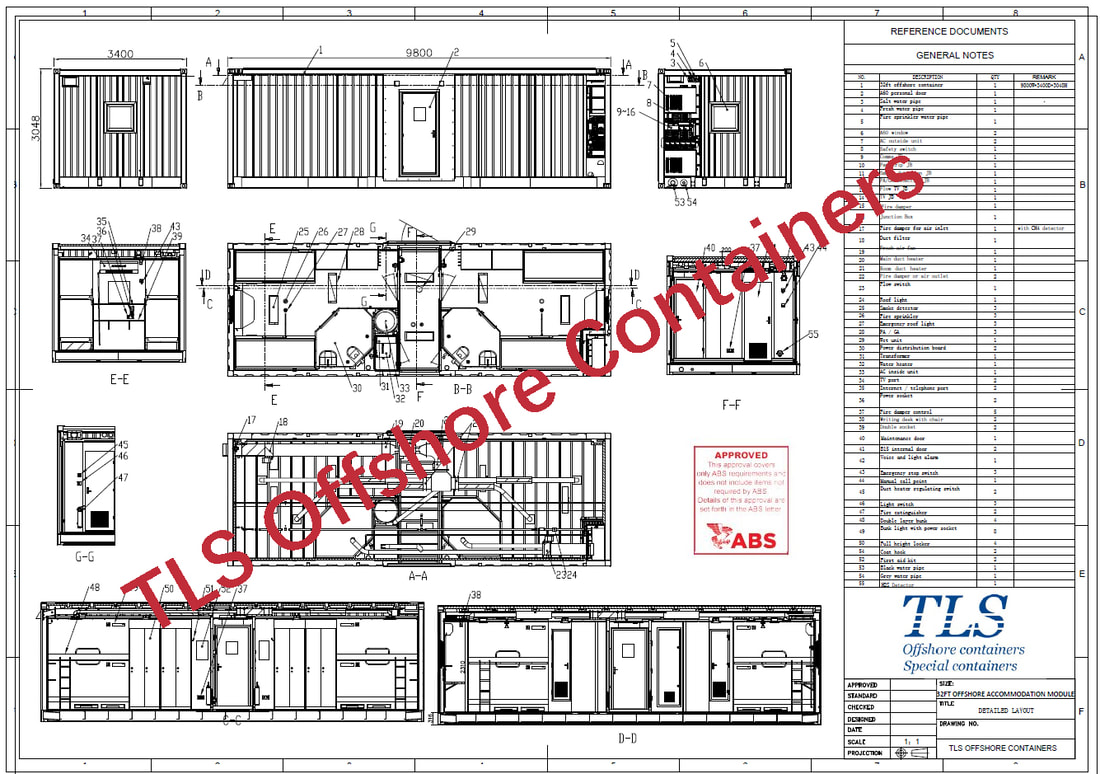 32FT offshore accommodation modules, 8 pax accommodation cabin, ABS approved offshore cabin In electrical and safety engineering, hazardous locations are places where fire or explosion hazards may exist. Sources of such hazards include gases, vapors, dust, fibers, and flyings, which are combustible or flammable. Electrical equipment installed in such locations could provide an ignition source, due to electrical arcing, or high temperature. Standards and regulations exist to identify such locations, classify the hazards, and design equipment for safe use in such locations. A light switch may cause a small, harmless spark when switched on or off. In an ordinary household this is of no concern, but if a flammable atmosphere is present, the arc might start an explosion. In many industrial, commercial, and scientific settings, the presence of such an atmosphere is a common, or at least commonly possible, occurrence. Equipment can be designed or modified for safe operation in hazardous locations. The two general approaches are: 1. Intrinsic safety Intrinsic safety, also called non-incendive, limits the energy present in a system, such that it is insufficient to ignite a hazardous atmosphere under any conditions. This includes low both power levels, and low stored energy. Common with instrumentation. 2. Explosion proof Explosion-proof or flame-proof equipment is sealed and rugged, such that it will not ignite a hazardous atmosphere, despite any despite sparks or explosion within. Several techniques of flame-proofing exist, and they are often used in combination:
Explosive Atmospheres - Part 13: Equipment Protection By Pressurized Room "P" And Artificially Ventilated Room "V" IEC 60079-13:2017(E) gives requirements for the design, construction, assessment, verification and marking of rooms used to protect internal equipment by pressurization or artificial ventilation or both as applicable when located in an explosive gas atmosphere or combustible dust atmosphere hazardous area with or without an internal source of a flammable gas or vapour. It also includes a room located in a non-hazardous area that has an internal source of release of a flammable gas or vapour. This document deals with rooms that are partially constructed in a manufacturer’s facility and intended to have the final installation completed on-site, as well as rooms that are constructed completely on-site. Rooms partially constructed in a manufacturer’s facility may include third-party verification. For rooms built on-site, this document can be used by plant operators as a guide for assessment of those facilities. This document represents a major technical revision of the requirements for equipment protection by pressurized room "p" and artificially ventilated room "v" and should be considered as introducing all new requirements. This second edition cancels and replaces the first edition published in 2010. This edition constitutes a technical revision. This edition includes the following significant technical changes with respect to the previous edition: - modification of the title of this document to include artificially ventilated room "v" in addition to pressurized room "p"; - addition of types of protection "pb", "pc", and "vc" and removal of types of protection "px", "py", "pz" and "pv"; - definition of the differences between pressurization and artificial ventilation types of protection; - removal of protection of rooms with an inert gas or a flammable gas from the scope of this document; - addition of an informative annex to include examples of applications where types of protection pressurization or artificial ventilation or pressurization and artificial ventilation can be used and associated guidelines. Keywords: marking of rooms used to protect internal equipment, pressurized room “p”, artificially ventilated room “v” IECEx System Objective
The objective of the IECEx System is to facilitate international trade in equipment and services for use in explosive atmospheres. while maintaining the required level of safety:
, reduced testing and certification costs to manufacturer , reduced time to market , international confidence in the product assessment process , one international database listing , maintaining International Confidence in equipment and services covered by IECEx Certification What is an Ex area? Ex areas can be known by different names such as "Hazardous Locations·. "Hazardous Areas· "Explosive Atmospheres·. and the like and relate to areas where flammable liquids, vapors, gases or combustible dusts are likely to occur in quantities sufficient to cause a fire or explosion. The modern day automation of industry has meant an increased need to use equipment in Ex areas. Such equipment is termed "Ex equipment" Where do you commonly find Ex equipment? Ex equipment in such areas include: , Automotive refuelling stations or petrol stations , Oil refineries, rigs and processing plants , Chemical processing plants , Printing industries, paper and textiles , Hospital operating theatres , Aircraft refuelling and hangars , Surface coating industries , Underground coal mines , Sewerage treatment plants , Gas pipelines and distribution centers , Grain handling and storage , Woodworking areas , Sugar refineries , Metal surface grinding, especially aluminum dusts and particles IECEx International Certification System In addition to the preparation of International Standards, the IEC facilitates the operation of Conformity Assessment Systems. One such System is the IECEx System The IECEx System comprises the following: , The IECEx Certified Equipment Scheme , The IECEx Certified Service Facilities Scheme , The IECEx Conformity Mark Licensing System , The IECEx Certification of Personnel Competencies 
Hazardous zone classification
This Technical Measures Document refers to the classification of plant into hazardous areas, and the systematic identification and control of ignition sources. The Dangerous Substances and Explosive Atmospheres Regulations 2002 (DSEAR) provide for the first time a specific legal requirement to carry out a hazardous area study, and document the conclusions, in the form of zones. General PrinciplesHazardous Area Classification for Flammable Gases and VapoursArea classification may be carried out by direct analogy with typical installations described in established codes, or by more quantitative methods that require a more detailed knowledge of the plant. The starting point is to identify sources of release of flammable gas or vapour. These may arise from constant activities; from time to time in normal operation; or as the result of some unplanned event. In addition, inside process equipment may be a hazardous area, if both gas/vapour and air are present, though there is no actual release. Catastrophic failures, such as vessel or line rupture are not considered by an area classification study. A hazard identification process such as a Preliminary Hazard Analysis (PHA) or a Hazard and Operability Study (HAZOP) should consider these abnormal events. The most commonly used standard in the UK for determining area extent and classification is BS EN 60079 part 101, which has broad applicability. The current version makes clear the direct link between the amounts of flammable vapour that may be released, the ventilation at that location, and the zone number. It contains a simplistic calculation relating the size of zone to a rate of release of gas or vapour, but it is not helpful for liquid releases, where the rate of vaporisation controls the size of the hazardous area. Other sources of advice, which describe more sophisticated approaches, are the Institute of Petroleum Model Code of Practice (Area Classification Code for Petroleum Installations, 2002), and the Institution of Gas Engineers Safety Recommendations SR25, (2001). The IP code is for use by refinery and petrochemical type operations. The IGE code addresses specifically transmission, distribution and storage facilities for natural gas, rather than gas utilisation plant, but some of the information will be relevant to larger scale users. ZoningHazardous areas are defined in DSEAR as "any place in which an explosive atmosphere may occur in quantities such as to require special precautions to protect the safety of workers". In this context, 'special precautions' is best taken as relating to the construction, installation and use of apparatus, as given in BS EN 60079 -10. Area classification is a method of analysing and classifying the environment where explosive gas atmospheres may occur. The main purpose is to facilitate the proper selection and installation of apparatus to be used safely in that environment, taking into account the properties of the flammable materials that will be present. DSEAR specifically extends the original scope of this analysis, to take into account non-electrical sources of ignition, and mobile equipment that creates an ignition risk. Hazardous areas are classified into zones based on an assessment of the frequency of the occurrence and duration of an explosive gas atmosphere, as follows:
When the hazardous areas of a plant have been classified, the remainder will be defined as non-hazardous, sometimes referred to as 'safe areas'. The zone definitions take no account of the consequences of a release. If this aspect is important, it may be addressed by upgrading the specification of equipment or controls over activities allowed within the zone. The alternative of specifying the extent of zones more conservatively is not generally recommended, as it leads to more difficulties with equipment selection, and illogicalities in respect of control over health effects from vapours assumed to be present. Where occupiers choose to define extensive areas as Zone 1, the practical consequences could usefully be discussed during site inspection. As an example:A proposal was made to zone an aircraft hanger as Zone 1, although the use of fuels handled above their flash point would be a rare event. It proved difficult to obtain a floor-cleaning machine certified for Zone 1 areas, though the floor needed sweeping regularly. The option of writing out an exception to normal instructions to allow a non Ex-protected machine to be used regularly is not recommended. Instead, a more realistic assessment of the zones is needed, and special instructions issued for the rare event of using more volatile fuels. A hazardous area extent and classification study involves due consideration and documentation of the following:
The results of this work should be documented in Hazardous Area Classification data sheets, supported by appropriate reference drawings showing the extent of the zones around (including above and below where appropriate) the plant item. Selection of EquipmentDSEAR sets out the link between zones, and the equipment that may be installed in that zone. This applies to new or newly modified installations. The equipment categories are defined by the ATEX equipment directive, set out in UK law as the Equipment and Protective Systems for Use in Potentially Explosive Atmospheres Regulations 1996. Standards set out different protection concepts, with further subdivisions for some types of equipment according to gas group and temperature classification. Most of the electrical standards have been developed over many years and are now set at international level, while standards for non-electrical equipment are only just becoming available from CEN. The DSEAR ACOP describes the provisions concerning existing equipment. There are different technical means (protection concepts) of building equipment to the different categories. These, the standard current in mid 2003, and the letter giving the type of protection are listed below. Zone 0Zone 1Zone 2 Category 1Category 2Category 3 'ia' intrinsically safe EN 50020, 2002'd' - Flameproof enclosure EN 50018 2000Electrical Type 'n' - EN 50021 1999 Non electrical EN 13463-1, 2001 Ex s - Special protection if specifically certified for Zone 0'p' - Pressurised EN 50016 2002 'q' - Powder filling EN 50017, 1998 'o' - Oil immersion EN 50015, 1998 'e' - Increased safety EN 50019, 2000 'ib' - Intrinsic safety EN 50020, 2002 'm' - Encapsulation EN 50028, 1987 's' - Special protection Correct selection of electrical equipment for hazardous areas requires the following information:
T1450>450 T2300>300 T3200>200 T4135>135 T5100>100 T685>85 If several different flammable materials may be present within a particular area, the material that gives the highest classification dictates the overall area classification. The IP code considers specifically the issue of hydrogen containing process streams as commonly found on refinery plants. Consideration should be shown for flammable material that may be generated due to interaction between chemical species. Ignition Sources - Identification and ControlIgnition sources may be:
Instead, safety should be achieved by a combination of a high standard of integrity of fuel and process pipelines, together with a means of rapid detection and isolation of any pipes that do fail. The consequences of the failure of a pipe carrying process materials within the furnace should be considered in any HAZOP study. Other processes (such as hot oil heating circuits) may handle products above their auto-ignition temperature. Any such processes should be specifically identified in a safety case. Again, area classification is not a suitable means of controlling the ignition risks, and the same considerations apply, as with fired heaters. Lightning ProtectionProtection against lightning involves installation of a surge protection device between each non-earth bonded core of the cable and the local structure. Further guidance can be found in BS 6651:19991 - (Code of practice for protection of structures against lightning). Ignitions caused by lightning cannot be eliminated entirely, particularly with floating roof tanks, where vapour is usually present around the rim seal. In these circumstances, measures to mitigate the consequences of a fire should be provided. VehiclesMost normal vehicles contain a wide range of ignition sources. These will include electrical circuits; the inlet and exhaust of any internal combustion engine; electrostatic build up; overheating brakes, and other moving parts. Site rules should be clear where normal road vehicles may be taken, and areas where they must be excluded. Standard EN 17551 sets out the requirements for diesel powdered ATEX category 2 or 3 lift trucks. Electric powered vehicles can also be built using a combination of this standard and the normal electrical standards. No specification is available for vehicles with spark ignition engines, and it is unlikely that such an engine could be built economically. Vehicles certified to ATEX requirements are however expensive, and for many applications an unprotected type has to be extensively rebuilt. Consequently, many employers are likely to try and justify not zoning storage compounds, where lift trucks handle flammable liquids or gases in containers. In some stores, perhaps with limited use of a vehicle, this may be acceptable. Discussions have been held with the British Chemical Distributors and Traders Association, with the objective of clarifying when storage areas should be classified as zone 2. The conclusions from this exercise will be made available in due course. Discussions are also ongoing, about vehicles with gas detection systems, designed to shut the engine and isolate other sources of ignition in the event of a gas release. At present these are sold without any claim for ATEX compliance, but with the suggestion they may be useful in cases of remote risk. For the purposes of COMAH, an assessment is needed of the risk that an ignition within a storage compound will produce a major accident, either directly or because a fire or explosion spreads to involve other materials. If this is possible, it is more appropriate to provide controls to prevent the spread, rather than simply apply more conservative zoning, and more restrictive rules on the equipment used in the store. Where specialist vehicles (e.g. cranes) are needed during maintenance operations, proper controls and plant isolation may allow the normal zones to be suspended. Typically these will involve written instructions, as specified in DSEAR schedule 1, or a formal permit to work system. Many sites will have operations of filling and emptying road tankers with flammable materials. Controls will be needed to prevent or minimise the release of gas or vapour but controls over ignition sources are also needed. Hazardous areas may be considered to exist during the transfer operation, but should not be present once the transfer is complete. Safe systems of work are needed to ensure safety where such 'transient' zones exist. Factors for Assessor of a Safety Case to Consider
DSEAR requires that hazardous area classification for flammable dusts should be undertaken in the same manner as that for flammable gases and vapours. Zoning as described above may be applied, replacing 'gas atmosphere' with 'dust/air mixtures'. The zone numbers used are 20, 21 and 22, corresponding to 0,1 and 2 used for gases/vapours The only relevant standard to help people zone their plant is BS EN 50281 part 3, 20021, which is an adaptation of the IEC equivalent. Where toxic dusts are processed, releases into the general atmosphere should be prevented, and the extent of any zone 21 or 22 outside the containment system should be minimal or non-existent. The inside of different parts of the plant may need to be zoned as 20, 21 or 22, depending on the conditions at particular locations. Classification of dusts relating to autoignition and minimum ignition current is undertaken similarly to gases/vapours, but involves additional complications. The explosibility of dusts is dependent upon a number of factors:
Ignition due to a hot surface is possible, but the temperature needed to ignite a dust layer depends on layer thickness and contact time. For COMAH sites with toxic dusts, the most likely hazard would arise in drying processes, if substantial quantities were held for extended periods hot enough to start self heating or smouldering combustion. Status of GuidanceExisting codes of practice provide information with respect to good practice for hazardous area classification. The standards detailing selection of appropriate electrical apparatus have been updated to take into consideration ventilation effects. European equipment standards may become 'harmonised' when a reference to them is published in the Official Journal of the European Community. A list of ATEX harmonised standards can be checked on the EU web site: Equipment built to such a harmonised standard may assume automatic conformity with those essential safety requirements of relevant directives that are covered by the standard. The EPS regulations describe the conformity assessment procedures that apply to different types of equipment. The fire proof system can be divided into two aspects, these are passive and active protection.
Active fire protection - manual and automatic detection and suppression of fires, For example: Fire or smoke detector system Fire alarm systems. Fire sprinkler systems Fire extinguisher Firefighter Passive fire protection (PFP) - The installation of fire rated walls, ceiling and floor assemblies to form fire compartments intended to limit the spread of fire, high temperatures, and smoke. For example: To improve fire resistance performance of material To paint the fire-retardant coating, such as cementitious and epoxy intumescent. To cover the insulated panel Fire Testing For PFP materials to be classified for offshore use they must meet three main fire-testing requirements that are commonly accepted. These are Standard fire test, Hydrocarbon pool fire test and Hydrocarbon jet fire test. Fire proof classification according to Standard Fire test There are three classification which are A, B and C class. 1. "A" class divisions: 1). They are constructed of steel or other equivalent material; 2). They are suitably stiffened; 3). They are constructed as to be capable of preventing the passage of smoke and flame to the end of the one-hour standard fire test; 4). They are insulated with approved non-combustible materials such that the average temperature of the unexposed side will not rise more than 140ºC above the original temperature, nor will the temperature, at any one point, including any joint, rise more than 180ºC above the original temperature, within the time listed below: Class "A-60” 60 min Class "A-30” 30 min Class "A-15” 15 min Class "A-0” 0 min 2. "B" class divisions: 1). They are constructed of approved non-combustible materials and all materials used in the construction and erection of "B" class divisions are non-combustible, with the exception that combustible veneers may be permitted provided they meet other appropriate requirements of this chapter; 2). They are constructed as to be capable of preventing the passage of flame to the end of the first half hour of the standard fire test; 3). They have an insulation value such that the average temperature of the unexposed side will not rise more than 140ºC above the original temperature, nor will the temperature at any one point, including any joint, rise more than 225ºC above the original temperature, within the time listed below: Class "B-15" 15 min Class "B-0" 0 min 3. "C" class divisions Divisions constructed of approved noncombustible materials. They need meet neither requirements relative to the passage of smoke and flame nor limitations relative to the temperature rise. Fire proof classification according to Hydrocarbon Pool Fire test "H" class divisions: 1. They are constructed of steel or other equivalent material; 2. They are suitably stiffened; 3. They are constructed as to be capable of preventing the passage of smoke and flame to the end of the two-hour standard fire test; 4. They are insulated with approved non-combustible materials such that the average temperature of the unexposed side will not rise more than 140ºC above the original temperature, nor will the temperature, at any one point, including any joint, rise more than 180ºC above the original temperature, within the time listed below: Class "H-120” 120 min Class "H-60” 60 min Class "H-0” 0 min Fire proof classification according to Hydrocarbon Jet Fire test "J" class divisions: 1. They are constructed of steel or other equivalent material; 2. They are suitably stiffened; 3. They are constructed as to be capable of preventing the passage of smoke and flame to the end of the first half hour standard fire test; 4. They are insulated with approved non-combustible materials such that the average temperature of the unexposed side will not rise more than 140ºC above the original temperature, nor will the temperature, at any one point, including any joint, rise more than 180ºC above the original temperature, within the time listed below: Class "J-60” 60 min Class "J-30” 30 min IEC 60079-13:2017 gives requirements for the design, construction, assessment, verification and marking of rooms used to protect internal equipment:
– located in a Zone 1 or Zone 2 or Zone 21 or Zone 22 explosive atmosphere without an internal source of gas/vapour release and protected by pressurization; – located in a Zone 2 explosive atmosphere with or without an internal source of gas/vapour release and protected by artificial ventilation; – located in a non-hazardous area, containing an internal source of gas/vapour release and protected by artificial ventilation; – located in a Zone 1 or Zone 2 or Zone 21 or Zone 22 explosive atmosphere containing an internal source of gas/vapour release and protected by both pressurization and artificial ventilation. The term "room" used in this document includes single rooms, multiple rooms, a complete building or a room contained within a building. A room is intended to facilitate the entry of personnel and includes inlet and outlet ducts. An acoustic hood and other like enclosures designed to permit the entry of personnel can be considered as a room. This document also includes requirements related safety devices and controls necessary to ensure that artificial ventilation, purging and pressurization is established and maintained. A room assembled or constructed on site, can be either on land or off-shore. The room is primarily intended for installation by an end-user but could be constructed and assessed at a manufacturer’s facility, where the final construction such as ducting can be completed on site. This document does not specify the methods that may be required to ensure adequate air quality for personnel with regard to toxicity and temperature within the room. National or other regulations and requirements may exist to ensure the safety of personnel in this regard. This second edition cancels and replaces the first edition published in 2010. This edition constitutes a technical revision. This edition includes the following significant technical changes with respect to the previous edition: a) modification of the title of this document to include artificially ventilated room "v" in addition to pressurized room "p"; b) addition of types of protection "pb", "pc", and "vc" and removal of types of protection "px", "py", "pz" and "pv"; c) definition of the differences between pressurization and artificial ventilation types of protection; d) removal of protection of rooms with an inert gas or a flammable gas from the scope of this document; e) addition of an informative annex to include examples of applications where types of protection pressurization or artificial ventilation or pressurization and artificial ventilation can be used and associated guidelines. 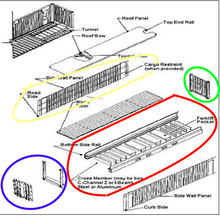 1. Basic frame
The base frame consists of two (2) lower side rails, several cross members and a gooseneck tunnel, which are welded together as a subassembly. 2.Front End The front end will be composed of corrugated end wall and front end frame, which are welded together as a sub-assembly. 3. Rear End Rear end is composed of Rear End Frame which consists of one door sill, two corner posts, one rear header with header plate and four corner fittings, which are welded together as a sub-assembly, and Door Systems with locking devices. 4.Side Wall Assembly Side Walls Each side wall will be composed of a number of sheets for the intermediate (inner) parts and outer panels at each end of side wall, fully vertically corrugated into trapezium section, butt welded together to form one panel by automatic welding. 5.Roof The roof will be constructed by several die-stamp corrugated steel sheets with a certain upwards camber at the center of each trough and corrugation, these sheets are butt jointed together to form one panel by automatic welding. 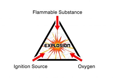 A hazardous area can be defined as any location where there is risk of an explosion. But every hazardous area is different and each has specific requirements depending on the nature of the atmosphere and the elements that are present.
Fundamentally, for an explosion to take place, flammable or explosive gases, vapours, mists or dusts will be present. Then, the level of risk of an explosion is based on the frequency and duration of the occurrence of an explosive atmosphere. This level of risk is represented by classifying the hazardous area as Zone 0, Zone 1 or Zone 2 (for gas, vapour and mist atmospheres) or Zone 21 or Zone 22 for dust atmospheres. we will look at what defines Zone 0, Zone 1 and Zone 2 hazardous area classifications and the considerations for specifying lighting into each area. But first, we must consider what is likely to cause an explosion in the first place. There are three necessary components for an explosion to occur; 1. Flammable Substance – this needs to be present in a relatively high quantity to produce an explosive mixture (e.g. gas, vapours, mists and dusts). 2. Oxygen – oxygen is required in high quantities and in combination with the flammable substance to produce an explosive atmosphere. 3. Ignition Source – a spark or high heat must also be present. Where there is potential for an explosive atmosphere, special precautions are needed to prevent fires and explosions. Electronic equipment, including lighting, needs to be purpose designed for use in hazardous areas to prevent a spark occurring and igniting any flammable substances. Although every application is different, for the ease of monitoring and specification each hazardous area is classified as a particular level or “zone”. As a result, all hazardous area equipment must be designed with hazardous area zone classifications in mind, as the “zone” governs the level of protection and precaution required. It is essential to know which zone you are working in, so that you can specify the most appropriate equipment. For gases, vapours and mists the zone classifications are recognised as Zone 0, Zone 1 and Zone 2 areas. Let’s take a look at what defines each zone…
|
- Home
-
Containerised solutions
- Intelligent pressurised container | MUD logging cabin
- Battery energy storage system (BESS) container
- Flexible grid tied battery storage system
- Laboratory container | workshop container | Equipment containers
- Temporary refuge shelter | Toxic gas refuge | Safe haven
- Offshore accommodation cabin | office container
- Reefer container | Refrigerated container
- Intelligent waste water treatment container
- Fresh water generator container
- Cargo Containers
- Product photos & videos
- News & Blogs
- Contact us
|
Featured products
Intelligent pressurised container Temporary refuge (TR) shelter, toxic gas refuge (TGR) Battery energy storage system (BESS) container Containerised waste water treatment plant Fresh water generator container Reefer container Laboratory container, Workshop container Accommodation container Offshore closed container |
All Rights Reserved 2020 © TLS Offshore Containers / TLS Energy
|