|
In the demanding landscape of the oil and gas industry, safety and efficiency are paramount. To navigate these challenges effectively, companies rely on robust equipment and infrastructure, especially in offshore environments. Here’s where DNV 2.7-1 certified offshore containers step in as game-changers. What is DNV 2.7-1 Certification? DNV 2.7-1 is a globally recognized standard developed by Det Norske Veritas (DNV), setting the bar for offshore container design, manufacture, testing, inspection, and certification. These containers are engineered to withstand extreme conditions while ensuring the safety of personnel and the environment. Benefits of DNV 2.7-1 Certified Offshore Containers:
Why Choose DNV 2.7-1 Certified Offshore Containers?
Partnering with TLS Offshore Containers: TLS Offshore Containers is a leading global supplier offering both standard and customized containerized solutions. With a commitment to quality and safety, TLS specializes in providing DNV 2.7-1 certified offshore containers tailored to meet diverse industry needs. Conclusion: DNV 2.7-1 certified offshore containers represent a cornerstone in the pursuit of safety and efficiency in the oil and gas sector. With their robust design, rigorous testing, and versatile applications, these containers empower companies to navigate challenges effectively while maintaining the highest standards of quality and compliance. For reliable container solutions, companies can trust TLS Offshore Containers to deliver excellence wherever they operate. TLS Offshore Containers / TLS Special Containers is a global supplier of standard and customised containerised solutions. Wherever you are in the world TLS can help you, please contact us. Key words: #Offshore containers #DNV 2.7-1 certification #Oil and gas industry #Safety #Efficiency #Versatility #Rigorous testing #Hazard protection #Customization Written by OliverIntroduction: In the realm of offshore operations, ensuring the safety and reliability of equipment is paramount. One key aspect that underscores this commitment to safety is the DNV 2.7-1 certification for offshore containers. This certification, issued by DNV (Det Norske Veritas), signifies compliance with international standards and plays a pivotal role in safeguarding both personnel and assets in the challenging offshore environment. Understanding DNV 2.7-1 Certification: DNV 2.7-1 is a standard developed by DNV to establish minimum requirements for offshore containers. These containers are widely used to transport goods, equipment, and materials to and from offshore platforms and vessels. The certification process involves a rigorous assessment of the container's design, manufacturing, and maintenance processes to ensure they meet stringent safety and quality standards. Key Elements of DNV 2.7-1 Certification:
Benefits of DNV 2.7-1 Certification:
Conclusion: In the complex and demanding world of offshore operations, the importance of DNV 2.7-1 certification for offshore containers cannot be overstated. This certification provides a robust framework for ensuring the safety, reliability, and regulatory compliance of containers, ultimately contributing to the success and sustainability of offshore projects. Companies that prioritize DNV 2.7-1 certification are not only investing in the well-being of their personnel but also in the longevity and efficiency of their offshore operations. TLS Offshore Containers / TLS Special Containers is a global supplier of standard and customised containerised solutions. Wherever you are in the world TLS can help you, please contact us. #DNV 2.7-1 certification #Offshore containers #Offshore operations #Safety standards #International regulations #Structural integrity #Material quality #Welding standards #Design assessment #Testing requirements 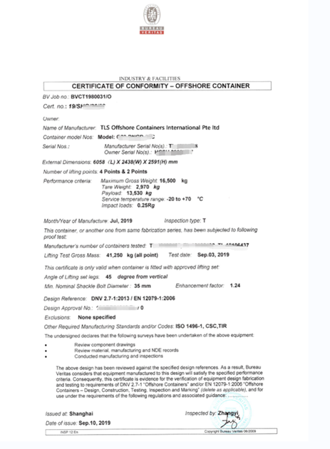 Written by OliverIntroduction: DNV (Det Norske Veritas) plays a crucial role in ensuring safety at sea and on land through its certification and verification services. In this article, we'll explore the key characteristics and benefits of DNV 2.7-1 certified offshore containers, highlighting their importance in harsh offshore conditions. DNV 2.7-1 Certification: What Sets Them Apart DNV 2.7-1 certified offshore containers are purpose-built for dynamic hoisting, equipped with eye pad devices and DNV certified slings with shackles. These containers undergo rigorous checks throughout their lifecycle, including the design phase, material procurement, production, and final loading, as well as Non-Destructive Examination (NDE) testing. Testing and Quality Assurance Unlike standard containers, DNV 2.7-1 containers are subject to meticulous testing procedures. Prototypes are rigorously tested, and a specific number of units from each batch are randomly selected for testing, ensuring a level of scrutiny five times higher than ISO standard containers. Robust Construction One of the distinguishing features of DNV 2.7-1 containers is their solid steel structure, which includes reinforced floors. These containers are designed to withstand the challenges of rough seas, making them substantially heavier compared to ISO containers of the same size. This added weight is essential to keep them upright during transportation in adverse conditions. DNV Approved Slings and Materials DNV 2.7-1 containers are equipped with DNV-approved slings and incorporate stronger steel. The production process adheres to strict specifications to ensure the highest quality. All test documentation is readily available to demonstrate their reliability in offshore environments. Certification Process Classification societies play a vital role in certifying offshore containers. The process involves:
Conclusion: DNV 2.7-1 certified offshore containers are engineered to meet the demanding needs of offshore industries. Their robust construction, rigorous testing, and adherence to DNV standards ensure their reliability in the harshest offshore conditions, making them a vital asset for maritime safety and efficiency. TLS Offshore Containers / TLS Special Containers is a global supplier of standard and customised containerised solutions. Wherever you are in the world TLS can help you, please contact us. #Shackles #Testing procedures #ISO standard containers #Robust construction #Steel structure #Offshore environments #Quality assurance #Manufacturing process #Welder qualifications #Non-destructive testing 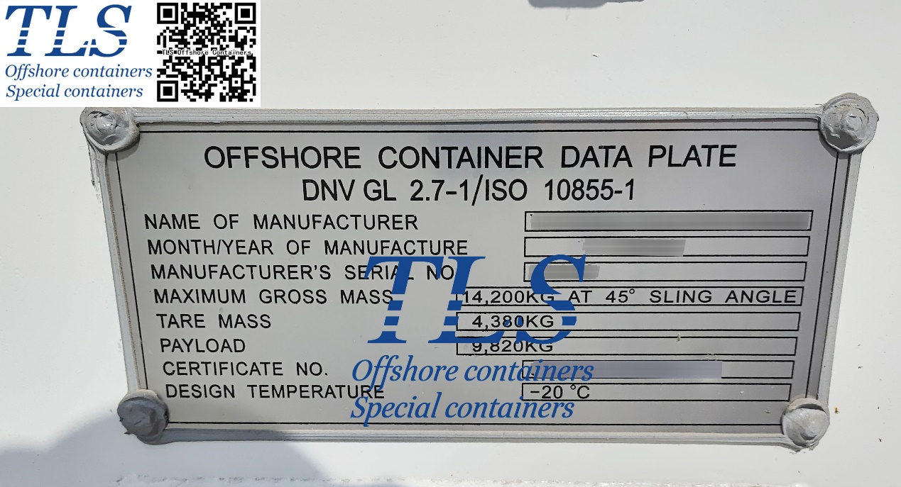 Written by OliverIntroduction In today's rapidly advancing industrial landscape, where technology and innovation are at the forefront, various industries such as oil and gas, chemicals, pharmaceuticals, and mining rely heavily on machinery and equipment to streamline their operations. However, these industries often operate in hazardous environments where the presence of flammable gases, vapors, and dust can pose significant safety risks. This is where the IEC 60079-13 certificate comes into play, ensuring the safe operation of equipment in explosive atmospheres. What is the IEC 60079-13 Certificate? The IEC 60079-13 certificate is a critical standard within the International Electrotechnical Commission (IEC) 60079 series, which sets the guidelines for equipment used in explosive atmospheres, also known as hazardous locations. IEC 60079-13 specifically deals with the installation and maintenance of electrical equipment in explosive gas atmospheres. This certificate ensures that electrical equipment, including motors, control panels, sensors, and other devices, is designed and maintained to prevent the ignition of potentially explosive atmospheres due to electrical sparks or other sources of energy. Why is the IEC 60079-13 Certificate Important?
Obtaining and Maintaining the Certificate To obtain the IEC 60079-13 certificate, manufacturers and operators must follow a series of steps:
Conclusion The IEC 60079-13 certificate is an indispensable tool for ensuring safety in industries that operate in hazardous environments. By adhering to the guidelines set out in this standard, businesses can mitigate the risks associated with explosive atmospheres, safeguard their personnel and assets, and contribute to a safer industrial landscape. With the increasing emphasis on safety regulations worldwide, obtaining and maintaining the IEC 60079-13 certificate is not just a legal requirement but a crucial step toward responsible and reliable industrial operations. TLS Offshore Containers / TLS Special Containers is a global supplier of standard and customised containerised solutions. Wherever you are in the world TLS can help you, please contact us. #IEC 60079-13 #Hazardous environments #Explosive atmospheres #Electrical equipment certification #Safety standards #Hazardous locations #Flammable gases #Compliance regulations #Industrial safety #Legal requirements 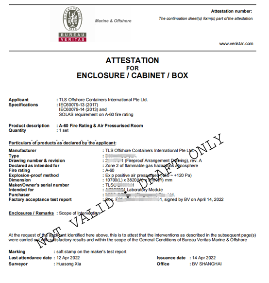 Written by OliverIACS stands for the International Association of Classification Societies. It is a non-governmental organization that comprises twelve classification societies from around the world. These societies work together to develop and promote standards for the design, construction, and maintenance of ships and other marine structures. Being an IACS member certified means that a classification society has been approved by IACS and is authorized to perform surveys and issue certificates for ships and other marine structures in accordance with the rules and regulations developed by IACS. This certification ensures that the classification society meets the high standards set by IACS and has the necessary expertise and resources to carry out its responsibilities in an effective and efficient manner. The current twelve members of IACS are:
The IACS member certification is important for several reasons:
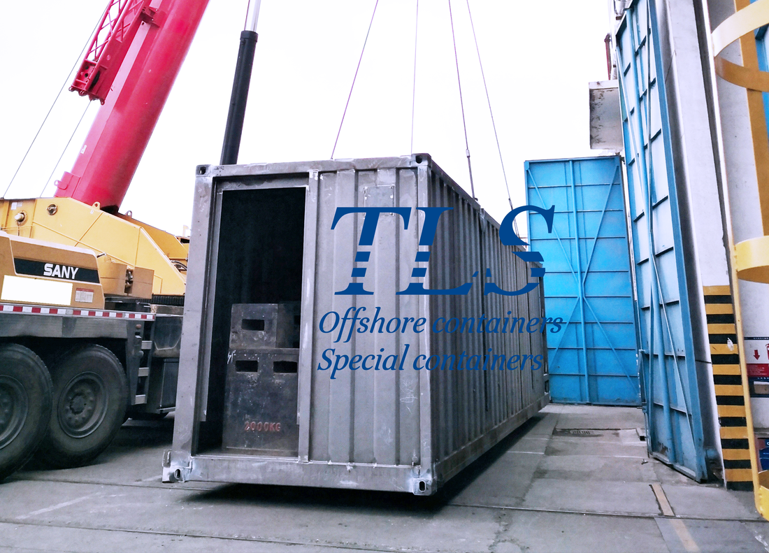
TLS is a global supplier of standard and customized containerized solutions. We've got 20 years experience for special container & 10 Years experience for modular building. Our containers meet the highest offshore standard. We are certified by many well-known classification. Wherever you are in the world TLS can help you, please contact us.  Written by OliverWhen it comes to offshore containers used in the oil and gas industry, DNV2.7-1 is a widely recognized standard. However, selecting the right paint standard for these containers can be challenging. Two options to consider are C3 and C5 standards. The C3 standard is suitable for containers used in general marine environments, with coatings having medium durability and anti-corrosion properties. The minimum paint thickness should be 75μm. On the other hand, the C5 standard is suitable for containers used in highly corrosive environments, with coatings having high durability and anti-corrosion properties. The minimum paint thickness should be 150μm. It's important to consider the specific usage environment and requirements when selecting the paint standard for DNV2.7-1 compliant containers. For general marine environments, the C3 standard is typically sufficient. However, if the container will be exposed to highly corrosive environments, the C5 standard should be used. Proper surface preparation, primer application, intermediate coats, and topcoat thickness are also crucial factors in ensuring the longevity and durability of the paint on DNV2.7-1 compliant containers. In conclusion, choosing the right paint standard is essential to ensure the safety and longevity of DNV2.7-1 compliant containers. By understanding the differences between C3 and C5 standards and considering the specific usage environment, you can make an informed decision and select the appropriate standard for your container. 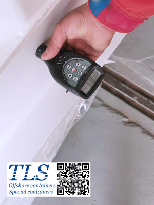 C5 PAINTING As defined by the International Maritime Organization, an offshore container is a "portable unit specially designed for repeated use in the transport of goods or equipment between fixed and/or floating offshore installations and ships. Known in the offshore oil and gas community as "slippery rails "as they are often used to transport large assemblies to drilling and production rigs. DNV's certification standards 2.7-1, 2 and 3 are a globally recognized set of certification standards for offshore containers and marine service modules. The certification standards relate to the certification of all types of marine containers as transport units. The three typical stages of transportation are: shore-based residency (eg, forklifts), supply vessels, and loading and unloading offshore facilities. The certification standards include design requirements related to all three phases. There are five basic steps for DNV approval and certification: 1. Certification of our (or our client's designation) written welding procedures, laboratory tests and welder qualifications 2. Evaluate and approve our primary device/skid/frame designs 3. Audit/Survey during initial welding start-up 4. Production:Audits/investigations during equipment manufacturing 5. Prototype testing:For "type" approval (type approval means a series of identical units are manufactured over a period) 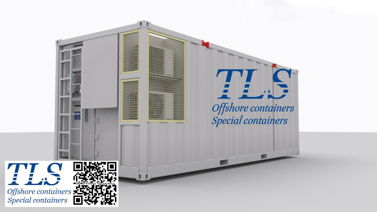 What is DNV certification? DNV (Det Norske Veritas), a Norwegian classification society, merged with Germanischer Lloyd (GL) in September 2013 to form the world's largest classification society DNV GL Group. As a classification society, DNV GL sets standards for the offshore, maritime, energy and oil and gas industries. The purpose of these standards is to provide users, operators and engineers with requirements, principles and acceptance criteria. Two common standards are:
DNV2.7-1 and DNV2.7-3 in common
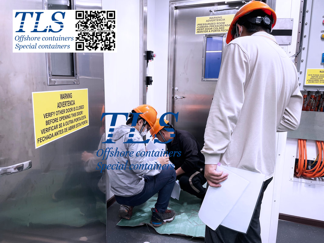
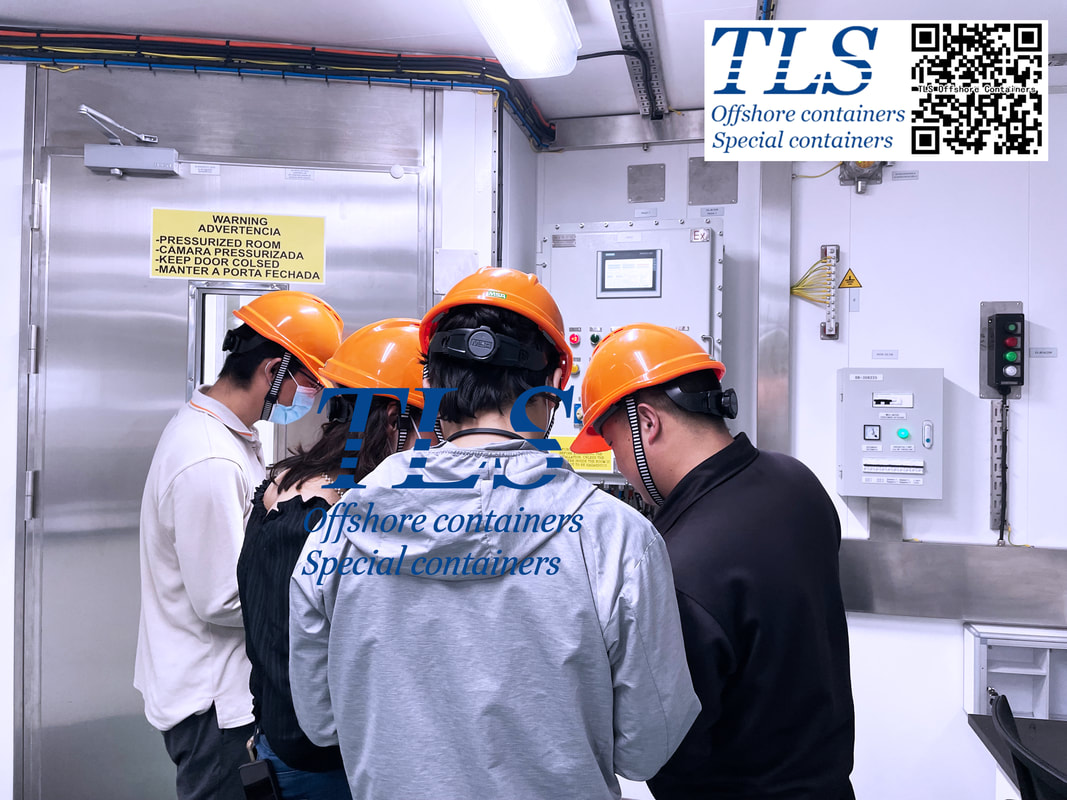
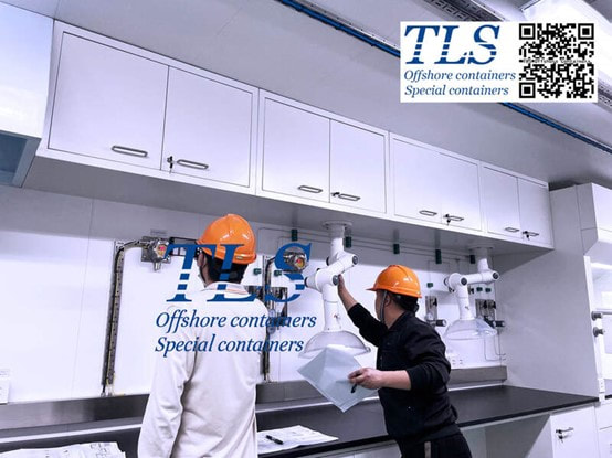
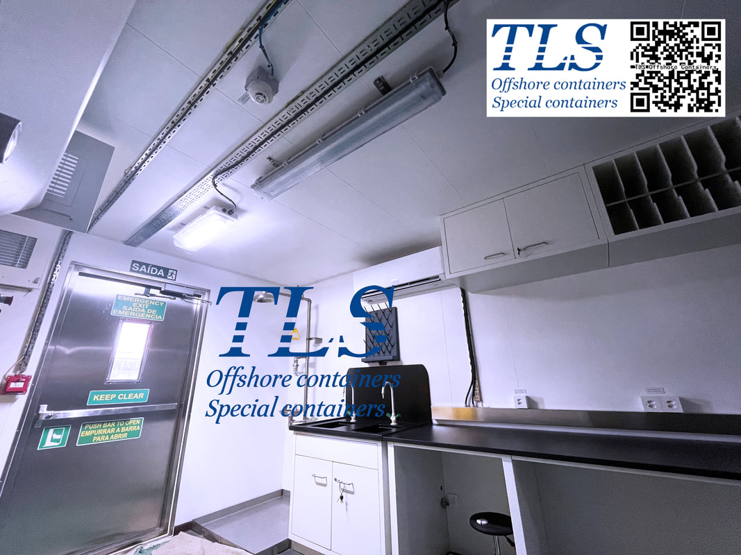
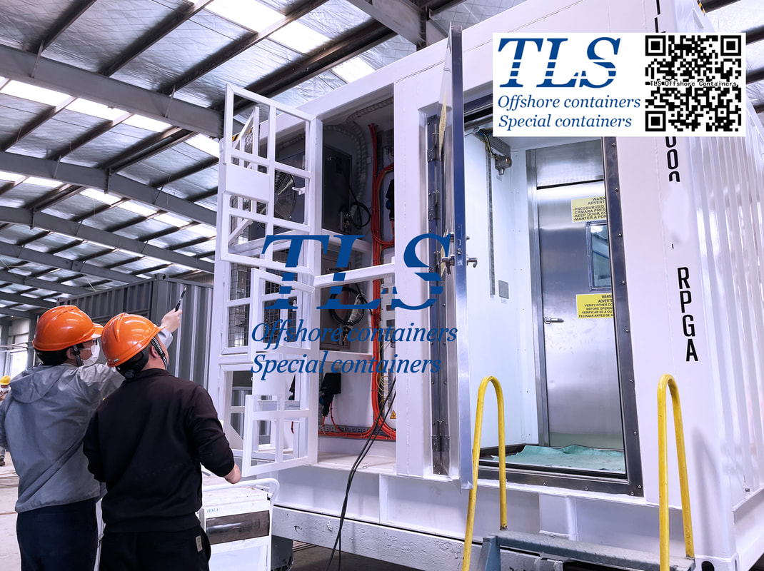
Difference between DNV2.7-1 and DNV2.7-3 Apart from the difference in standard details, the biggest difference is that the maximum gross weight (MGW) of dnV2.7-1 certified container is less than 25,000 kgs, and the MGW of DNV2.7-3 certified container is greater than 25,000 kgs. Although DNV2.7-1 and DNV2.7-3 standards are set by DNV Classification Society, they are also recognized by other classification societies (BV, LRs, etc), which will issue corresponding certificates according to the same standards.  The specially designed ultra-wide explosion-proof lab container|workshop container| Pressure container is about to be delivered. Our technicians are cooperating with various inspections from the end customer and SGS to ensure that the performance of the container meets customer standards and industry standards. TLS provides DNV2.7-1 standard | explosion-proof | which can be used in hazardous areas (ZONE 0, ZONE 1, AND ZONE 2) | special containers that meet A60 fire rating, we provide the independent certification from DNV | BV | LR | ABS | SGS. Any requirements, please contact us directly: E-mail: [email protected] Hotline: +65-65637288; +65-31386967 Key words: #DNV #BV #LR #ABS #SGS #DNV2.7-1 #ESS #BESS #A60 fire rating #explosion-proof #LAB # workshop container #TLS offshore containers 1 WELDING INSPECTION |
- Home
-
Containerised solutions
- Intelligent pressurised container | MUD logging cabin
- Battery energy storage system (BESS) container
- Flexible grid tied battery storage system
- Laboratory container | workshop container | Equipment containers
- Temporary refuge shelter | Toxic gas refuge | Safe haven
- Offshore accommodation cabin | office container
- Reefer container | Refrigerated container
- Intelligent waste water treatment container
- Fresh water generator container
- Cargo Containers
- Product photos & videos
- News & Blogs
- Contact us


|
Featured products
Intelligent pressurised container Temporary refuge (TR) shelter, toxic gas refuge (TGR) Battery energy storage system (BESS) container Containerised waste water treatment plant Fresh water generator container Reefer container Laboratory container, Workshop container Accommodation container Offshore closed container |
All Rights Reserved 2020 © TLS Offshore Containers / TLS Energy
|