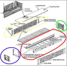
 1. Basic frame
The base frame consists of two (2) lower side rails, several cross members and a gooseneck tunnel, which are welded together as a subassembly. 2.Front End The front end will be composed of corrugated end wall and front end frame, which are welded together as a sub-assembly. 3. Rear End Rear end is composed of Rear End Frame which consists of one door sill, two corner posts, one rear header with header plate and four corner fittings, which are welded together as a sub-assembly, and Door Systems with locking devices. 4.Side Wall Assembly Side Walls Each side wall will be composed of a number of sheets for the intermediate (inner) parts and outer panels at each end of side wall, fully vertically corrugated into trapezium section, butt welded together to form one panel by automatic welding. 5.Roof The roof will be constructed by several die-stamp corrugated steel sheets with a certain upwards camber at the center of each trough and corrugation, these sheets are butt jointed together to form one panel by automatic welding. 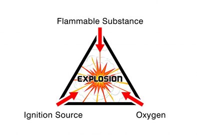 A hazardous area can be defined as any location where there is risk of an explosion. But every hazardous area is different and each has specific requirements depending on the nature of the atmosphere and the elements that are present.
Fundamentally, for an explosion to take place, flammable or explosive gases, vapours, mists or dusts will be present. Then, the level of risk of an explosion is based on the frequency and duration of the occurrence of an explosive atmosphere. This level of risk is represented by classifying the hazardous area as Zone 0, Zone 1 or Zone 2 (for gas, vapour and mist atmospheres) or Zone 21 or Zone 22 for dust atmospheres. we will look at what defines Zone 0, Zone 1 and Zone 2 hazardous area classifications and the considerations for specifying lighting into each area. But first, we must consider what is likely to cause an explosion in the first place. There are three necessary components for an explosion to occur; 1. Flammable Substance – this needs to be present in a relatively high quantity to produce an explosive mixture (e.g. gas, vapours, mists and dusts). 2. Oxygen – oxygen is required in high quantities and in combination with the flammable substance to produce an explosive atmosphere. 3. Ignition Source – a spark or high heat must also be present. Where there is potential for an explosive atmosphere, special precautions are needed to prevent fires and explosions. Electronic equipment, including lighting, needs to be purpose designed for use in hazardous areas to prevent a spark occurring and igniting any flammable substances. Although every application is different, for the ease of monitoring and specification each hazardous area is classified as a particular level or “zone”. As a result, all hazardous area equipment must be designed with hazardous area zone classifications in mind, as the “zone” governs the level of protection and precaution required. It is essential to know which zone you are working in, so that you can specify the most appropriate equipment. For gases, vapours and mists the zone classifications are recognised as Zone 0, Zone 1 and Zone 2 areas. Let’s take a look at what defines each zone…
|
- Home
-
Containerised solutions
- Intelligent pressurised container | MUD logging cabin
- Battery energy storage system (BESS) container
- Flexible grid tied battery storage system
- Laboratory container | workshop container | Equipment containers
- Temporary refuge shelter | Toxic gas refuge | Safe haven
- Offshore accommodation cabin | office container
- Reefer container | Refrigerated container
- Intelligent waste water treatment container
- Fresh water generator container
- Cargo Containers
- Product photos & videos
- News & Blogs
- Contact us
|
Featured products
Intelligent pressurised container Temporary refuge (TR) shelter, toxic gas refuge (TGR) Battery energy storage system (BESS) container Containerised waste water treatment plant Fresh water generator container Reefer container Laboratory container, Workshop container Accommodation container Offshore closed container |
All Rights Reserved 2020 © TLS Offshore Containers / TLS Energy
|