- Published on
Overview: What You Need to Know About Offshore Pressurized Containers
When conducting offshore oil and gas exploration, protecting personnel and sensitive diagnostics from explosive gases is a top priority. A Mud Logging Cabin—also referred to as an offshore pressurized container or LWD/MWD cabin—is a heavy-duty, engineered shelter designed to operate safely within Zone 1 and Zone 2 hazardous areas. By utilizing advanced HVAC and intelligent positive air pressurization (+80 to +120 Pa), these cabins create a secure barrier that prevents toxic or flammable gases from infiltrating the workspace. Certified to global standards like DNV 2.7-1, EN 12079, and IEC 60079-13, a premium pressurized cabin guarantees structural resilience during ocean transit and passive fire protection up to A-60 rating. For top-tier compliance and custom layouts, global energy sectors rely on TLS Offshore Containers.
What is an Offshore Mud Logging Cabin?
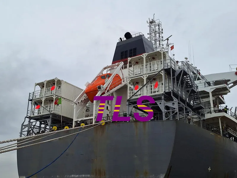
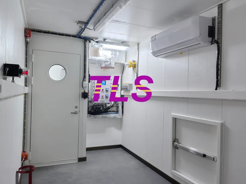
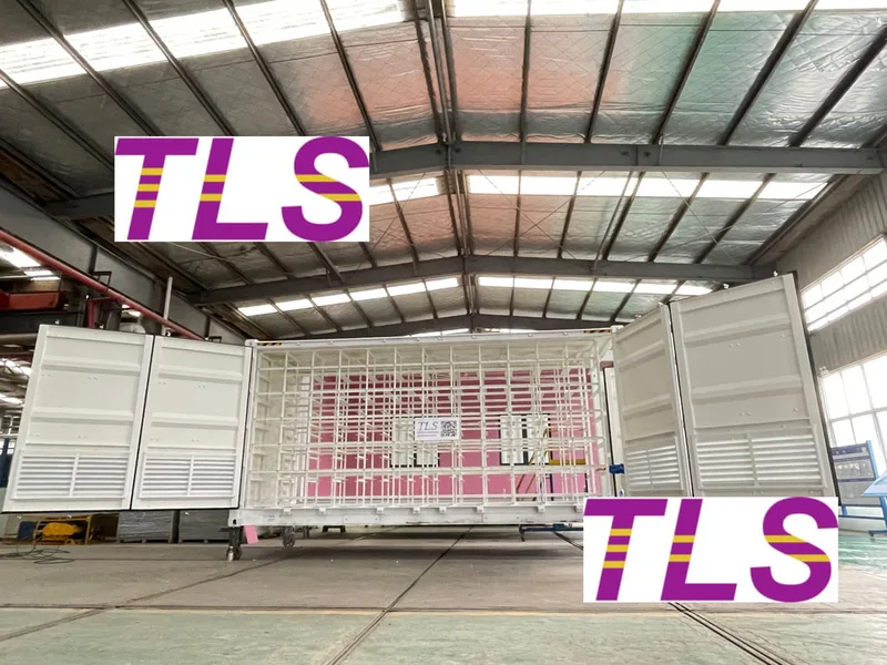
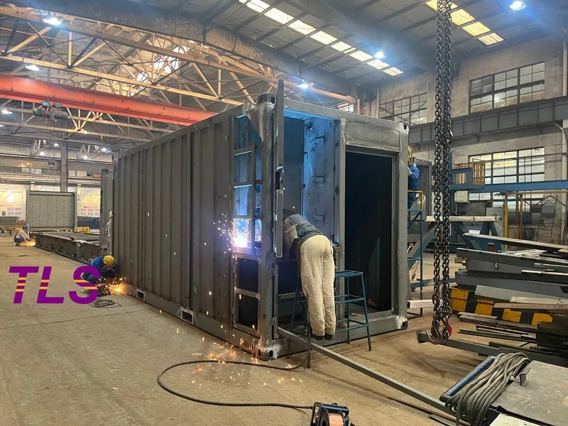
In the challenging environment of offshore oil and gas development, a Mud Logging Cabin serves as the control hub and primary shelter for complex logging instrument systems. Whether engineers are performing mud chemical analysis, tracking geological data, or managing measurement-while-drilling (MWD) systems, they require a workspace that isolates them from the volatile external atmosphere.
Because these units are deployed in areas where flammable vapors may be present, they are strictly rated as Zone 1 and Zone 2 hazardous area enclosures. The defining mechanism of these units is their positive pressure system, which maintains a safe internal pressure of +80 to +120 Pa, constantly pushing air outward so that hazardous external elements cannot leak inside.
Technical Performance and Design Specifications
For procurement managers and offshore engineers looking for detailed dimensional and technical compliance, TLS Mud Logging Cabins are engineered to the following rigorous technical standards:
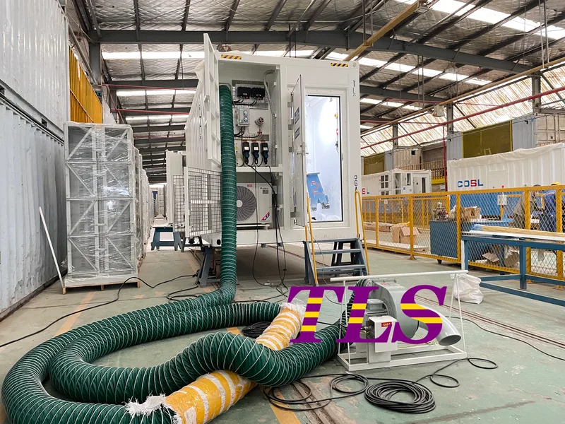
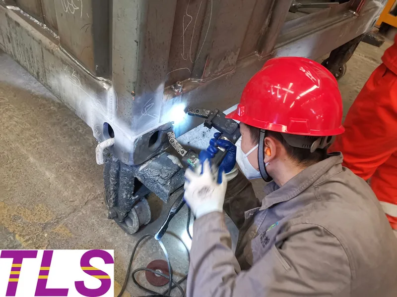
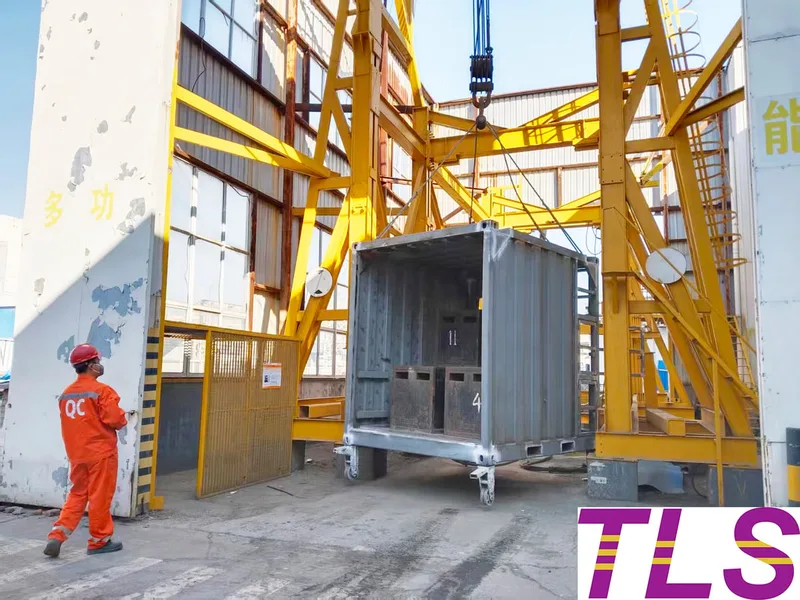
- Structural Integrity: The structural design fully complies with DNV 2.7-1 and EN 12079 structural design codes. Each cabin is subjected to full load and drop testing to ensure zero deformation during crane lifting and sea freight.
- Premium Fire Protection: Built to satisfy the applicable requirements of SOLAS 2009, the cabin features A-60 passive fire protection. The walls, roof, and endwalls are composed of T3.0mm SPA-H weathering steel, integrated with t60 A60 Rockwool and T30mm rock wool sandwich panels. The floor consists of a T30mm A60 deck topped with a T2.0mm checkered steel plate and T1.6mm PVC vinyl.
- Electrical and Power Systems: Certified under IEC 60079-13, the main power supply supports versatile international offshore voltages including 380V, 440V, 480V, 600V, and 690V AC (3PH+PE) at both 50Hz and 60Hz.
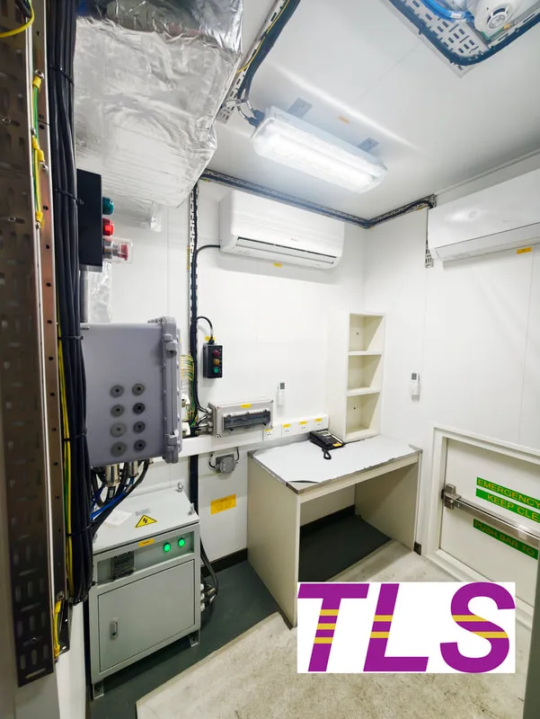
- Access and Safety Outfitting: Access is secured via an airlock entrance system featuring an A60 rated fire door (or specialized roller shutter) along with an A60 emergency escape hatch. Optional fixtures include dedicated oxygen and nitrogen gas inputs, and explosion-proof transformers with 110V output configurations.
Core Features: Why TLS Pressurized Containers Lead the Market
1. Intelligent Fire & Gas Control (CPFG System)
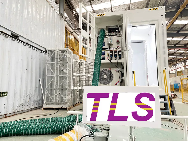
The safety of a TLS Mud Logging Unit relies on its Intelligent Combined Pressurisation Fire & Gas Panel (CPFG). This programmable, PLC-based system serves as the cabin's brain, continuously regulating the internal climate. It integrates ATEX-compliant or Ex-proof air conditioning alongside Ex-approved pressurization fans. If high-sensitivity fire, smoke, flammable gas, or toxic (H2S) detectors sense a breach, the fail-safe automatic fire dampers close, and the system executes an automated emergency shutdown (ESD) to protect the team inside.
2. Uncompromising Global Compliance
Operating globally means meeting different maritime regulations. TLS cabins eliminate regulatory friction by carrying trusted third-party certifications from world-renowned classification societies such as DNV, Bureau Veritas (BV), and Lloyd’s Register (LR). Complying with ATEX and IECEx ensures that every switch, light, and wire is safe for explosive atmospheres.
3. Ultimate Durability and Customized Layouts
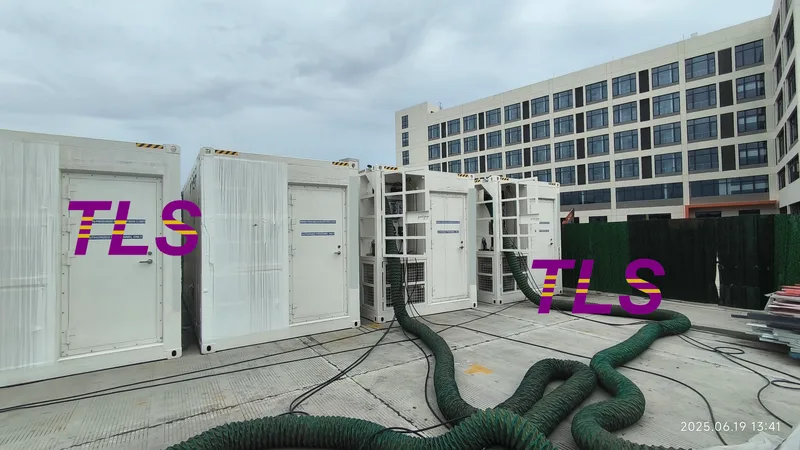
Using high-grade SPA-H anti-corrosive steel ensures that the cabin remains unyielding against saltwater corrosion and extreme wave impacts. Beyond standard dimensions, TLS provides deep customization. Cabins can be scaled from 10ft, 15ft, 20ft, to 40ft layouts, and pre-fitted with specialized lab workbenches, data communication networks, and localized climate controls to match your exact project scope.
Versatile Applications in Offshore Energy
While engineered perfectly as a Mud Logging Unit, these robust pressurized shelters are highly versatile and frequently utilized across the offshore industry as:
- MWD / LWD Cabins: Protecting sensitive downhole data recording electronics.
- Offshore Laboratories: Providing a safe, clean, and controlled environment for chemical analysis.
- Motor Control Centre (MCC) & Switchgear Shelters: Safeguarding VFD, VSD, and high-voltage power distribution systems in hazardous zones.
- ROV Control Rooms & Safe Havens: Serving as blast-resistant, sound-insulated control spaces or temporary refuge shelters for crew members.
Frequently Asked Questions
Q1: What is the primary purpose of positive pressure in an offshore cabin?
Positive pressure (+80 to +120 Pa) ensures that the atmospheric pressure inside the cabin is higher than the outside environment. If a door is opened or a tiny seal breach occurs, air flows outward, preventing dangerous flammable gases or toxic vapors (H2S) common in Zone 1 or Zone 2 areas from entering the cabin.
Q2: What is the difference between A-60 and A-0 fire ratings for offshore containers?
An A-60 rating means the cabin's insulation can prevent the temperature on the unexposed side from rising more than 139°C above the original temperature for a full 60 minutes during a standard fire test. An A-0 rating means the structure stops flames and smoke but does not offer the same thermal insulation time. TLS cabins utilize premium rock wool insulation to achieve the maximum A-60 safety standard.
Q3: What logisitcal options and warranties are available for TLS cabins?
TLS offers global transport coordination across Ocean, Railway, and Road networks, with standard structural lead times averaging 70 days. To guarantee long-term asset value, TLS provides a 1-year structural warranty, a 3-year painting warranty, and a 5-year decal warranty.
Partner with TLS for Your Next Offshore Venture
Do not compromise on safety or regulatory compliance. TLS Offshore Containers delivers the structural toughness and intelligent asset protection your offshore exploration projects demand.
TLS Offshore Containers / TLS Energy is a global supplier of standard and customised containerised solutions.
Wherever you are in the world, TLS can help you. Please contact us.
Product brochures:
Offshore total pressurised container solutions
Offshore pressurised mud logging cabin brochure
MCC | Switchgear | VFD | VSD pressurised shelter
- Published on
Executive Summary
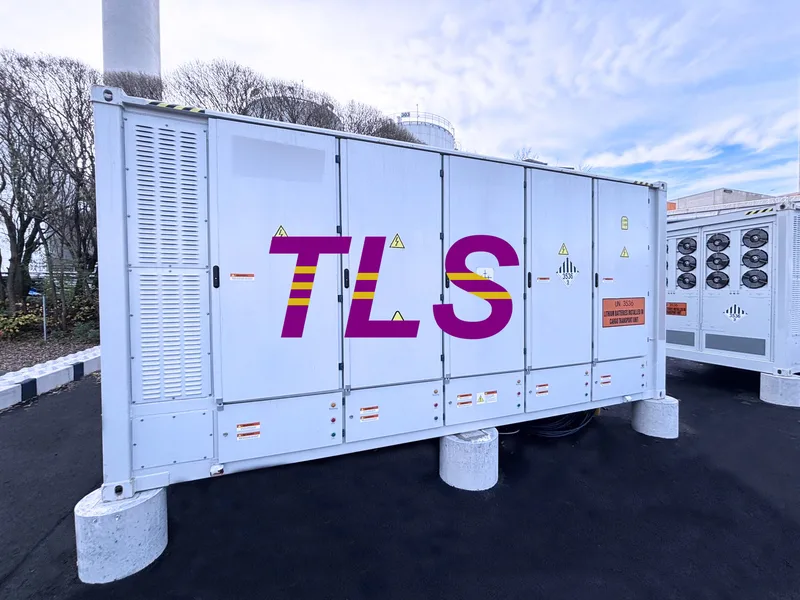
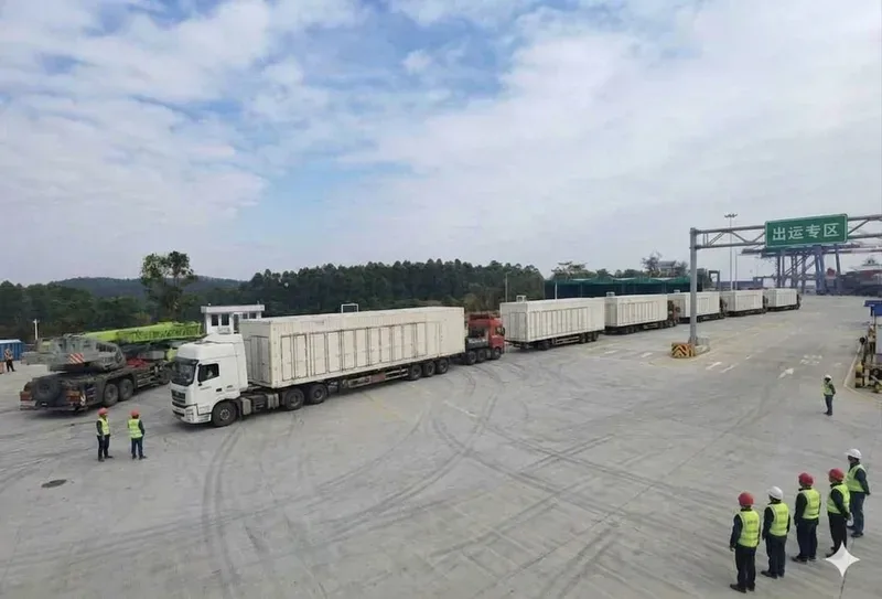
As renewable energy deployment, grid flexibility requirements, and commercial energy optimization needs continue to grow, the 20ft containerized Battery Energy Storage System (BESS) has become one of the most widely adopted solutions worldwide.
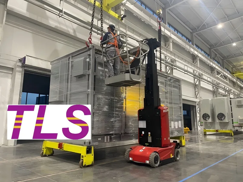
A 20ft BESS integrates batteries, Battery Management System (BMS), thermal management, fire protection, power distribution, and monitoring systems into a standard ISO container. With factory integration and pre-commissioning, it enables fast deployment, high safety reliability, and optimized lifecycle cost (LCOS).
Today, it is widely used in utility-scale renewable energy, grid stabilization, commercial & industrial storage, and microgrid applications.
Key Highlights
- Standard 20ft ISO container design for global transport compatibility
- Typical capacity ranges from 3MWh to 6MWh per unit
- Factory pre-integration reduces on-site installation time significantly
- Supports modular expansion for large-scale energy storage projects
- Designed for long lifecycle operation with optimized LCOS
What Is a 20ft BESS?
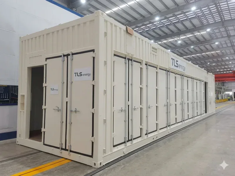
A 20ft Battery Energy Storage System (BESS) is a modular energy storage solution designed within a standard 20-foot ISO shipping container.
It integrates the following core systems:
- Battery packs (typically LFP chemistry)
- Battery Management System (BMS)
- Power conversion interface (PCS-ready design)
- Thermal management system (air or liquid cooling)
- Fire detection and suppression system
- Electrical distribution and control system
Because all major components are assembled and tested in a controlled factory environment, the system can be delivered as a near plug-and-play solution, requiring only site-level electrical connection.
Why Is the 20ft BESS Becoming So Popular?
The 20ft format has become the industry preference for several practical engineering and logistics reasons.
1. Standardized Global Transport
The 20ft ISO container is a globally accepted shipping standard, making logistics simpler and more cost-efficient for international projects.
2. Higher Energy Density in a Compact Footprint
Advances in LFP battery technology allow more energy to be stored within the same container size, improving land-use efficiency for large projects.
3. Faster Project Deployment
Since most assembly, wiring, and testing are completed in the factory, on-site installation time is significantly reduced.
4. Modular Expansion Capability
Multiple 20ft units can be combined to scale from small commercial systems to multi-hundred MWh utility-scale storage plants.
Typical Capacity of a 20ft BESS
Depending on system design and battery configuration, common capacities include:
- ~3 MWh systems
- ~5 MWh systems
- Up to ~6 MWh high-density systems
Higher-capacity designs are increasingly used in utility-scale projects to maximize energy output per land area.
TLS provides multiple configuration options based on project requirements, balancing energy density, safety, and operational performance.
What Matters Beyond Capacity?
While capacity is often the first specification considered, long-term system performance depends on multiple engineering factors.
Battery Safety
Most modern systems use Lithium Iron Phosphate (LFP) batteries due to their strong thermal stability and safety performance. Combined with advanced BMS control and fire protection systems, this significantly reduces operational risks.
Thermal Management
Stable temperature control directly affects battery efficiency and lifespan. Systems may use air cooling or liquid cooling depending on project conditions.
Fire Protection System
A multi-layer fire protection design typically includes early detection, system-level alarms, and suppression technologies to enhance operational safety.
Smart Monitoring & Control
Modern BESS platforms support remote monitoring, fault diagnosis, and predictive maintenance to improve uptime and reduce operational cost.
System Compatibility
PCS compatibility and modular architecture allow integration with different inverter brands and future system upgrades.
Where Are 20ft BESS Systems Used?
Thanks to their modular design and scalability, 20ft BESS solutions are widely deployed in:
- Utility-scale solar power plants
- Wind energy storage projects
- Grid frequency regulation and stabilization
- Commercial & industrial energy storage
- Microgrids and off-grid systems
- AI data centers and backup power systems
- Diesel hybrid and remote energy systems
Multiple units can be configured to meet different project sizes and energy demands.
How Does a BESS Improve LCOS (Levelized Cost of Storage)?
The total cost of an energy storage project is not only defined by initial investment.
Over the system lifetime, key cost drivers include:
- Battery degradation rate
- Thermal management efficiency
- System availability and reliability
- Maintenance requirements
- Replacement and expansion costs
A well-designed BESS reduces operational uncertainty and improves long-term return on investment by maintaining stable performance over its lifecycle.
TLS Containerized 20ft BESS Solutions
TLS provides modular 20ft containerized BESS solutions designed for different application scenarios.
Depending on project requirements, TLS can deliver:
- Battery container enclosure (structural solution)
- Semi-integrated BESS container system
- Fully integrated turnkey BESS solution
Each system can be customized with thermal management, fire protection, electrical design, and monitoring systems according to project specifications.
TLS solutions are engineered to support utility-scale renewable energy, industrial power systems, and commercial energy storage applications.
Frequently Asked Questions (FAQ)
Q1: Why is the 20ft BESS widely used?
Because it balances transport efficiency, energy density, and global standardization, making it suitable for most storage projects.
Q2: Is higher capacity always better?
Not necessarily. The optimal design depends on project goals, land availability, cost structure, and grid requirements.
Q3: Air cooling vs liquid cooling—what is better?
Both are widely used. The choice depends on climate conditions, system scale, and efficiency requirements.
Q4: Can the system be expanded later?
Yes. Modular BESS architecture allows capacity expansion by adding additional units.
Q5: What industries use 20ft BESS the most?
Renewable energy, utilities, commercial & industrial sectors, data centers, and microgrids are the main applications.
Conclusion
The 20ft containerized Battery Energy Storage System (BESS) has become a global standard for modern energy storage projects. Its modular design, standardized logistics, fast deployment capability, and scalable architecture make it suitable for a wide range of applications.
As battery technology continues to improve, 20ft BESS solutions will play an increasingly important role in supporting renewable integration, grid stability, and industrial energy optimization.
With extensive experience in modular container engineering, TLS Offshore Containers provides customized 20ft BESS solutions that deliver safe, reliable, and efficient energy storage infrastructure for global projects.
TLS Offshore Containers / TLS Energy is a global supplier of standard and customised containerised solutions.
Wherever you are in the world, TLS can help you. Please contact us.
- Published on
Executive Summary
As data centers, industrial facilities, and renewable energy projects continue to demand faster deployment and higher power reliability, modular E-Houses have become an increasingly popular alternative to traditional electrical buildings. A containerized Electrical House (E-House) integrates medium-voltage switchgear, transformers, low-voltage distribution, UPS systems, batteries, and environmental controls into a factory-built enclosure. This approach reduces on-site construction, shortens project schedules, and provides a standardized, scalable power infrastructure solution. In this article, you'll learn:
- What is an E-House?
- Why are more projects choosing modular E-Houses?
- What systems can be integrated into a TLS E-House?
- Where are modular E-Houses commonly used?
What Is an E-House?
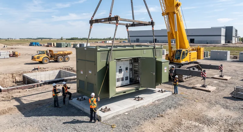
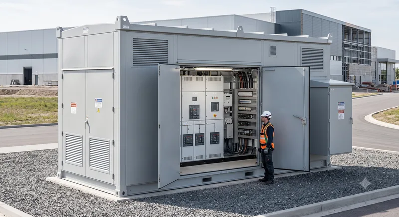
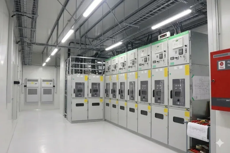
An Electrical House (E-House) is a prefabricated enclosure that houses electrical distribution and control equipment in a single modular unit. It is also known as a Containerized E-House, Modular Electrical House, Power Distribution Shelter, or Containerized Substation.
Instead of installing equipment individually on site, the electrical system is assembled, wired, and tested in the factory before shipment. Once delivered, only external connections are required, helping reduce installation time and simplify project execution.
Why Are More Projects Choosing Modular E-Houses?
Traditional electrical buildings require civil construction, equipment installation, field wiring, and on-site commissioning, all of which can extend project schedules.
A modular E-House offers several advantages:
- Factory-built and factory-tested before delivery
- Reduced on-site installation work
- Faster project completion
- Standardized quality and easier maintenance
- Flexible transportation and future expansion
- Suitable for remote or space-constrained locations
These benefits make modular E-Houses a practical choice for projects where construction time and operational reliability are critical.
E-House vs. Traditional Electrical Buildings
Both solutions perform the same electrical distribution function, but they differ in how they are delivered.
Traditional electrical buildings are generally constructed on site and are well suited for permanent facilities with longer construction schedules.
A modular E-House is manufactured off site, allowing electrical equipment to be installed and tested before delivery. This approach can reduce field work and simplify installation, making it well suited for data centers, renewable energy projects, industrial plants, mining operations, and other fast-track developments.
What Can Be Integrated into a TLS E-House?
TLS designs E-Houses according to individual project requirements and can integrate a complete range of electrical systems within a single enclosure.
Medium- and Low-Voltage Distribution
Medium-voltage switchgear, dry-type transformers, low-voltage switchboards, and diesel generator incoming panels can be integrated to provide a complete power distribution solution.
UPS and Backup Power
UPS systems, lithium battery cabinets, Static Transfer Switches (STS), and maintenance bypass panels can be configured to support uninterrupted power for critical equipment.
Environmental Control
Depending on the application, the enclosure can be equipped with precision air conditioning, industrial HVAC systems, and dehumidifiers to maintain suitable operating conditions for electrical equipment.
Cable Management
Separate cable routing for power and control circuits, together with cable trays and busbar systems, helps improve installation quality and simplifies maintenance.
Fire Protection
Fire detection, alarm systems, emergency control panels, and other safety features can be integrated according to project requirements.
Where Are Modular E-Houses Used?
Modular E-Houses are suitable for a wide range of industries, including:
- Data centers and AI computing facilities
- Industrial manufacturing plants
- Oil and gas projects
- Offshore platforms
- Wind and solar power plants
- Battery Energy Storage Systems (BESS)
- Mining operations
- Ports and infrastructure projects
- Microgrids and diesel power stations
- Remote industrial sites
Because every project is different, TLS can customize enclosure dimensions, equipment layout, and electrical configuration to meet specific operational requirements.
What Standards and Certifications Can an E-House Meet?
Depending on project requirements, TLS can design and manufacture E-Houses in accordance with applicable international standards.
Certification options may include DNV, BV, LR, and CSC, supporting offshore applications, international transportation, and project-specific compliance requirements.
Frequently Asked Questions
1. Does an E-House include a transformer?
Yes. Dry-type transformers can be integrated as part of the complete electrical distribution system.
2. Can UPS batteries be installed inside the enclosure?
Yes. Industrial lithium battery systems can be configured according to project requirements.
3. Can the E-House connect to a diesel generator?
Yes. Incoming panels for diesel generators can be incorporated when backup power is required.
4. How is the internal environment controlled?
Precision air conditioning, HVAC systems, and dehumidifiers can be installed to control temperature and humidity.
5. Can the enclosure be customized?
Yes. Dimensions, equipment layout, electrical ratings, and internal configuration can all be customized.
6. Are offshore applications supported?
Yes. E-Houses can be designed for offshore environments and supplied with classification society certification when required.
7. What certifications are available?
Certification options include DNV, BV, LR, CSC, or other project-specific requirements.
Conclusion
Modular E-Houses provide a practical alternative to conventional electrical buildings by combining electrical equipment into a factory-built, transportable enclosure. This approach reduces on-site installation, shortens project schedules, and simplifies future expansion.
With experience in designing and manufacturing customized modular container solutions, TLS Offshore Containers provides E-House systems tailored to the requirements of data centers, industrial facilities, offshore projects, and renewable energy applications.
- Published on
Overview: The Next-Gen "Digital Assistant" for High-Density Computing
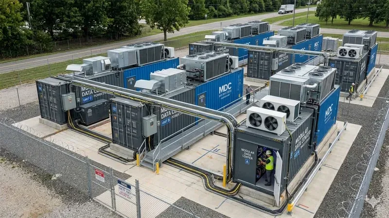
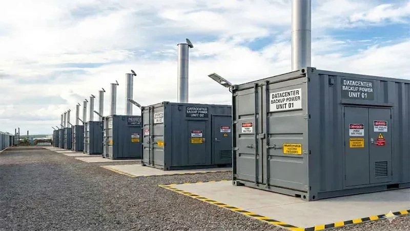
A Data Center Container (also known as a prefabricated modular data center) acts as the functional "heart" of the modern digital world, continuously delivering a stable "blood supply" for 5G edge networks, AI inference, and industrial automation. Rather than building traditional, fixed-location concrete facilities, modern enterprises deploy these factory-prefabricated, standardized 20ft and 40ft modular "building blocks."
By packing computing, energy storage, network, power systems, precision HVAC, and smart security into a unified, compact space, containerized solutions turn complex infrastructure into an efficient, portable, and responsive asset.
Key Capabilities of TLS Integrated Data Centers:
- The "All-in-One" Treasure Box: Integrates IT equipment racks, Power Distribution Units (PDUs), Uninterruptible Power Supply (UPS), battery systems, and fire suppression within a certified ISO structure.
- Closed Aisle Containment Technology: Features advanced closed cold/hot aisle isolation, maximizing cooling efficiency and reducing overall Power Usage Effectiveness (PUE) to extreme economic thresholds.
- Edge-Optimized Deployment: Purpose-built to sit adjacent to 5G base stations, smart manufacturing plants, and automotive robotics to process massive localized data streams with ultra-low latency.
- Continuous Intelligent O&M: Built to sustain uninterrupted 24/7/365 heavy duty operations through remote parameter tracking, automatic alarms, and AI-driven predictive fault analysis.
1. Breaking the Construction Paradigm: Factory Prefabrication
Traditional data center builds are notoriously slow, plagued by fragmented field-work involving separate teams for walls, floors, structural cabling, and mechanical routing.
- The TLS Edge: TLS re-engineers this approach by treating the data center as a unified product rather than a civil engineering project. Every critical micro-module—including precision air conditioning, intelligent power management, and server cabinets—is pre-fabricated, mounted, and fully debugged within a tightly controlled factory environment. When the container arrives at your event, industrial site, or remote location, deployment and final commissioning are completed in a fraction of traditional timelines, shortening your investment return cycle significantly.
2. Micro-Module Innovation: Core Components Working in Harmony
Inside the rugged structural shell of a TLS Containerized Data Center, every cubic centimeter is optimized. The architecture functions like an integrated organism:
- The Power Distribution Cornerstone: High-capacity PDUs and advanced UPS networks ensure a continuous, surge-protected flow of power to sensitive IT clusters.
- Precision Airflow & Thermal Regulation: High-density computing racks generate massive heat. TLS integrates in-row cooling and chilled water systems designed to maintain strict temperature and humidity ranges, safeguarding server stability even under maximum processing stress.
- Standardized O&M Interfaces: Because the placement, structural wiring, and interface configurations of each module are strictly standardized, ongoing maintenance and future hardware upgrades are exceptionally straightforward.
3. The Digital Lifeline: Uninterrupted 24/7 Smart Maintenance
A containerized data center may be highly portable, but its operation requires rigorous, enterprise-grade reliability. Daily Infrastructure Operation and Maintenance (O&M) is the lifeline that prevents critical downtime.
- Intelligent Tracking Technology: TLS data center enclosures are integrated with autonomous sensory arrays. These smart systems automatically capture environmental parameters (temperature, humidity, leakage, and electrical current profiles), sending live alerts to a centralized dashboard. This allows duty personnel or remote engineering teams to execute predictive maintenance, tracking subtle performance trends and resolving potential vulnerabilities long before a hardware failure can disrupt your digital ecosystem.
4. Seamless Synergy with the Ancillary Energy Grid
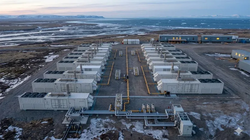
A digital heart requires a robust energy source. To ensure total uptime during a primary grid failure, TLS containers are engineered to integrate seamlessly with modular backup power blocks.
- Automatic Power Transfer: In the event of an outage, integrated automatic transfer switches (ATS) instantly bridge the system to high-durability Backup Generator Set Containers.
- E-House Integration: For larger network nodes, the data center couples directly with modular Electrical House (E-House) Containers, managing high-voltage transformation, power distribution, and grounding protections in complete synchronization.
5. Multi-Industry Adaptability: From 5G to Smart Manufacturing
The flexibility of the TLS Containerized Data Center makes it a universal digital assistant across a wide spectrum of modern high-growth sectors:
- The Internet & Financial Sectors: Efficiently processing and securing massive user traffic data with maximum physical and digital isolation.
- 5G Edge Networks: Rapidly expanding processing capability near remote communication towers to minimize network latency.
- Automobile & Industrial Plants: Acting as a localized processing node right on the factory floor, handling real-time data generated by heavy industrial robots, automated assembly lines, and IoT sensors simultaneously.
Conclusion: Scalable Infrastructure Built for the Digital Economy
As the velocity of digital transformation accelerates, containerized data centers offer the modularity, extreme portability, and rapid ROI that traditional construction models simply cannot match. TLS provides the specialized engineering precision, structural integrity, and smart integration capabilities required to keep your business-critical data moving seamlessly.
TLS Offshore Containers / TLS Energy is a global supplier of standard and customised containerised solutions.
Wherever you are in the world, TLS can help you. Please contact us.
- Published on
Overview: The Modular Paradigm Shift in Data Infrastructure
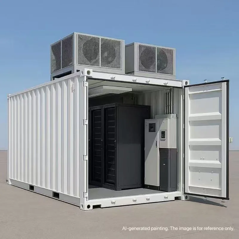
A Containerized Data Center (CDC)—also known as a prefabricated modular data center—is a portable, self-contained infrastructure solution that integrates computing racks, precision cooling, smart power distribution, and fire suppression within a ruggedized, standard-sized shipping container.
As traditional brick-and-mortar data centers struggle with long construction cycles and the thermal demands of high-density AI workloads, containerized solutions have emerged as the gold standard for rapid deployment.
As a global leading provider of precision-engineered modular enclosures, TLS Offshore Containers (TLS) is at the forefront of this architectural shift. In this article, we explore why containerized data centers are replacing traditional construction and how they empower businesses to scale at the speed of AI.
Key Quick Facts & Capabilities of TLS Containerized Data Centers:
- Unmatched Speed: Reduces deployment timelines by up to 70% compared to traditional civil construction, turning years into weeks.
- AI-Ready Density: Engineered to support advanced liquid cooling and closed-loop airflow, handling dense GPU clusters (30kW–100kW+ per rack) effortlessly.
- Turnkey Versatility: Available as high-spec structural enclosures or fully integrated, "plug-and-play" systems.
- Extreme Adaptability: Designed with robust weather-proofing and structural integrity for harsh remote sites, industrial hubs, and Edge computing networks.
- Ancillary Ecosystem: Seamlessly interfaces with modular E-Houses (Electrical Rooms) and Generator Set Containers for a comprehensive power grid.
Industry Insight: By converting massive upfront CAPEX into a scalable "Pay-As-You-Grow" OPEX model, containerized data centers allow tech enterprises and cloud providers to expand their infrastructure linearly, aligning perfectly with the volatile scaling demands of modern machine learning.
1. Speed to Market: From Years to Weeks
In the digital race, time-to-market is everything. Constructing a traditional concrete data center involves lengthy zoning permissions, civil engineering, and complex onsite integration, often taking 12 to 24 months.
- The TLS Solution: Our Containerized Data Centers utilize a modular "plug-and-play" framework. Built and pre-commissioned in our advanced factory environment, these units compress deployment timelines from years into mere weeks. Once delivered to your site, they require minimal infrastructure setup, allowing you to go live and monetize your computing cluster almost instantly.
2. Built for AI High-Density Workloads & Advanced Cooling
Traditional data centers are built for standard CPU racks (typically 5kW to 10kW per rack). However, AI training and inference utilizing heavy GPU clusters demand upwards of 30kW to 100kW+ per rack, generating intense thermal loads that standard air conditioning cannot handle.
- The TLS Solution: TLS containerized environments are specifically engineered to support advanced liquid cooling and high-precision closed-loop ventilation systems. We design customized structural layouts that isolate hot/cold aisles efficiently, ensuring your high-performance AI hardware runs at optimal PUE (Power Usage Effectiveness) without risk of thermal throttling.
3. Flexible Engagement Models: Enclosure vs. Fully Integrated
At TLS, we understand that every engineering project has unique boundary conditions. To accommodate varying project scopes, we offer two flexible engagement models:
- High-Spec Enclosures: Durable, ISO-standard, or bespoke modular shells engineered for supreme structural integrity, ideal for clients who prefer to install their own internal server infrastructure.
- Fully Integrated Systems: Ready-to-deploy turnkey solutions. These feature factory-installed equipment—including IT racks, precision cooling units, fire suppression, security, and smart monitoring—complete with comprehensive onsite commissioning.
4. Supporting the Ancillary Ecosystem: E-Houses & Gensets
A data center is only as reliable as its power and backup infrastructure. True scalability requires the entire ecosystem to be modular.
Beyond the core IT container, TLS designs and manufactures specialized ancillary containerized units:
- Containerized Electrical Rooms (E-Houses): Factory-built, highly secure power distribution hubs featuring complete UPS backups, voltage adaptation, and smart grounding systems.
- Containerized Generator Sets (Gensets): Ruggedized, weather-proof, and sound-attenuated enclosures that provide rapid-response backup power for mission-critical applications.
5. Smart Safety & "Pay-As-You-Grow" CAPEX Efficiency
A modern container from TLS is not just a steel shell; it is a smart safety hub. Integrated with real-time monitoring sensors, our units constantly track temperature, humidity, smoke, and pressure variations, providing automated alerts to eliminate operational risks.
Furthermore, instead of risking massive upfront CAPEX on an oversized concrete facility, containerized solutions enable a "Pay-As-You-Grow" financial model. You expand your infrastructure linearly by adding more TLS modules only when your data or AI workloads demand it.
Conclusion: Partner with TLS for Your Next-Gen Infrastructure
Whether you are deploying localized Edge nodes in harsh environments or scaling massive AI inference clusters, TLS delivers the ruggedized, cost-efficient, and precision-engineered environments your business needs.
With our massive 400,000 square meters manufacturing base and years of engineering expertise, TLS provides cost-competitive, world-class containerized solutions delivered globally.
TLS Offshore Containers / TLS Energy is a global supplier of standard and customised containerised solutions.
Wherever you are in the world, TLS can help you. Please contact us.
- Published on
Summary
An offshore accommodation container is a functional module designed to provide temporary or long-term living space for offshore workers. It is widely used on oil and gas platforms, offshore wind installation vessels, pipe-laying ships, engineering support vessels, and onshore remote sites like mining areas, deserts, and polar regions. Compared to standard ISO containers, offshore living modules must withstand frequent lifting, marine corrosion, harsh weather, and continuous operation, requiring higher standards in structure, safety, and equipment.
Why Must Offshore Accommodation Containers Comply with International Standards?
Offshore living modules are not just living spaces; they are critical facilities to protect personnel safety. International projects usually require containers to meet DNV 2.7-1 and EN 12079 standards to ensure safe sea-land transport, offshore lifting, and long-term service. Meanwhile, CSC certification allows global shipping and multi-modal transport. For project owners, compliance with international standards means higher safety, smoother inspections, and easier project delivery.
What Key Configurations Should a High-Quality Offshore Living Container Have?
1. Extreme Weather Resistance
Offshore equipment is exposed to high salt spray, high humidity, and extreme climates. TLS Offshore Containers designs 20ft living modules to operate in environments from -30°C to 70°C. The exterior uses a C5-grade marine anti-corrosion coating to increase corrosion resistance and extend service life.
2. A60 Fireproof Standard
Offshore living areas require strict fire safety. TLS accommodation containers use an A60 fireproof insulation structure and self-closing A60 fire doors. The ventilation system features active fire dampers, and the bathroom has an independent mechanical exhaust to reduce fire and smoke risks.
3. Marine-Grade Electrical and HVAC Systems
To reduce on-site installation work, the electrical system is fully integrated before leaving the factory, using marine-grade flame-retardant cables. For hot climates, it features a split marine air conditioning system (4P) with two T3-class high-temperature indoor units, perfect for regions like the Middle East.
4. Plug-and-Play Quick Deployment
On-site construction time is highly limited. TLS containers feature a plug-and-play design with pre-installed freshwater inlets, greywater outlets, blackwater outlets, and standard power connections, allowing fast pipeline hookups on site.
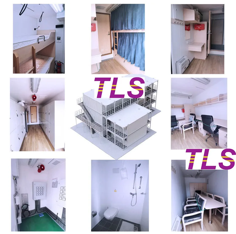
5. Comfortable Long-Term Living Space
The standard two-bedroom, one-bathroom layout accommodates two workers. Each room includes a single bed, wardrobe, desk, and office chair, with pre-wired connections for TV, internet, and phone. The bathroom includes a 60L water heater (5000W-6000W) and heater fans for all-weather use.
Where Can TLS Offshore Accommodation Containers Be Applied?
Beyond traditional oil and gas platforms, these 20ft containers are ideal for:
- Offshore wind installation and maintenance vessels
- Marine engineering and construction ships
- Pipe-laying vessels
- Polar research bases
- Desert and mining camps
- Integrated temporary office and living projects
Based on project needs, they can also be customized into single executive cabins or office-living combo units, and can work seamlessly with Gangway modules.
Frequently Asked Questions (FAQ)
Q1: What temperature range can these accommodation containers handle?
A: They are designed to operate from -30°C to 70°C, suitable for polar regions and hot seas.
Q2: What international certifications are required?
A: Standard certifications include DNV 2.7-1, EN 12079, and CSC. BV or LR classification society certifications are also optional.
Q3: Why is the A60 fire rating so important?
A: The A60 standard provides a longer protection time during a fire, which is a standard safety requirement for offshore living quarters.
Q4: Can these containers be used for onshore projects?
A: Yes. Remote sites like mining areas, deserts, and polar camps widely use these modular living solutions.
Conclusion
An offshore accommodation container is more than a mobile room; it is an integrated solution combining structural safety, fire protection, anti-corrosion, HVAC, electrical systems, and quick deployment. TLS Offshore Containers provides customized, certified offshore living solutions tailored to various marine engineering and onshore extreme environment projects.
TLS Offshore Containers / TLS Energy is a global supplier of standard and customised containerised solutions.
Wherever you are in the world, TLS can help you. Please contact us.
- Published on
What Is a CDU, and Why Should You Care?
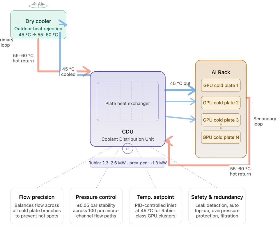
Think of a CDU — short for Coolant Distribution Unit — as the hydronic control hub of a liquid-cooled server rack. Just as a home radiant heating system uses a manifold to distribute hot water from a boiler to individual room circuits and return it in a continuous loop, a CDU distributes chilled coolant from a facility's external cooling plant to every GPU cold plate inside a rack, then collects the heated fluid on the return path.
The elegance of the CDU lies in what it keeps separate. Inside every CDU is a plate heat exchanger — a compact device made of corrugated metal plates that allows thermal energy to transfer between two fluid streams without the fluids ever mixing. On one side flows the facility's primary coolant loop, circulating between the CDU and an outdoor dry cooler that rejects heat to the ambient air. On the other side flows the secondary loop, which travels directly through the cold plates pressed against the GPUs.
This two-loop architecture is more than an engineering preference. It's a containment strategy. Outdoor water circuits can harbor minerals, biological growth, and contaminants. Keeping that fluid entirely separate from the precision microchannel cold plates protecting million-dollar accelerators is not optional — it's essential.
Precision, Not Just Plumbing
What separates a CDU from a glorified water pump is its ability to manage three interdependent variables simultaneously: flow rate, pressure, and temperature.
Inside a single high-density AI rack, dozens of GPU cold plates may be operating in parallel. Each accelerator has a different thermal profile depending on its workload. The CDU must apportion coolant flow to each branch with enough precision that no chip starves for cooling — while simultaneously avoiding excess flow that wastes pump energy and stresses the plumbing. Hydraulic balancing across dozens of parallel circuits is a genuinely hard fluid dynamics problem, and it's one that cheap or poorly engineered CDUs fail at consistently.
Pressure management is even less forgiving. Modern GPU cold plates use microchannel flow paths just 100 microns wide — roughly the width of a human hair. These structures are extraordinarily efficient at pulling heat out of silicon, but they are also fragile. A pressure spike can crack a flow channel and flood a rack. A sustained pressure drop means insufficient coolant circulation and thermal runaway. The CDU must maintain stability within tolerances of ±0.05 bar across thousands of operating hours.
Temperature control closes the loop. For NVIDIA's Rubin-generation GPU clusters, the secondary side inlet temperature must hold steady at approximately 45°C. The CDU achieves this through a combination of variable-frequency pump control and modulation of the heat exchange rate on the primary side — governed by PID control algorithms that continuously read sensor data and adjust outputs in real time. This isn't thermostat logic. It's feedback-driven thermal management running at the systems level.
The Rubin Challenge: Twice the Power, the Same Space
The demands on CDU engineering have escalated sharply with each GPU generation, but the leap to Rubin-class infrastructure is particularly striking.
Where previous-generation GB-series racks required CDUs with roughly 1.3 MW of cooling capacity, Rubin racks demand 2.3 to 2.6 MW — approximately double — while the physical footprint of the CDU expands by only 200 millimeters in width. Engineers must fit twice the thermal throughput into roughly the same cabinet envelope. This requires fundamentally more efficient plate heat exchangers, higher-performance pump impellers engineered to minimize vibration and noise at elevated power levels, and a control architecture sophisticated enough to manage not just one rack but an entire coordinated tier of AI compute infrastructure.
There is also a reliability tension that the industry has not yet fully resolved. Traditional CDU design specifies redundant pumps so that a single hardware failure does not take down an entire rack. But the space constraints of Rubin-class CDUs have pushed some vendors to eliminate pump redundancy, trading a well-established safety margin for physical feasibility. The consequence — increased single-point-of-failure risk in racks worth tens of millions of dollars — is a trade-off the industry is still actively debating.
Why CDU Expertise Is a Genuine Moat
The precision engineering required to build a reliable CDU at Rubin-class specifications explains why capable suppliers remain scarce. Accurate multi-circuit flow balancing, sustained micron-level pressure stability, closed-loop temperature control, integrated leak detection, automatic fluid replenishment, and predictive fault logic — these are not features that can be bolted on after the fact. They reflect deep, accumulated expertise in fluid mechanics, materials science, embedded control systems, and large-scale thermal simulation.
As GPU power densities continue to climb and liquid cooling transitions from premium option to baseline requirement, the CDU will only grow in strategic importance. Understanding what a CDU actually does — and what distinguishes an exceptional one from an adequate one — is no longer optional knowledge for anyone involved in AI infrastructure planning, data center procurement, or cooling system design.
The GPU gets the headlines. The CDU keeps it alive.
- Published on
Many engineering teams ask the same questions before selecting an offshore laboratory container:
- When should an offshore laboratory use positive pressure or negative pressure?
- Why are explosion-proof equipment and gas detection systems both necessary?
- How can a laboratory remain safe if gas is detected or pressure is lost?
This article explains the basic principles of intelligent pressure control in offshore laboratories and shows how TLS designs containerized laboratory solutions to improve safety, reliability, and compliance for Zone 1 and Zone 2 applications.
Positive Pressure or Negative Pressure? It Depends on the Laboratory Application
Pressure control is one of the most important safety features in an offshore laboratory.
For laboratories installed near hazardous areas, positive pressure is commonly used. Clean air is continuously supplied into the container so that the internal pressure remains higher than the outside atmosphere. This prevents flammable gases from entering the laboratory and creates a safe environment for personnel and equipment.
However, laboratories handling hazardous chemicals or volatile samples may require negative pressure. In this case, air flows into the laboratory rather than out, preventing harmful gases generated during testing from escaping into surrounding work areas.
The correct pressure strategy should always be determined by the laboratory process and project risk assessment.
Why Explosion-Proof Equipment Alone Is Not Enough
A common misconception is that explosion-proof electrical equipment alone can guarantee laboratory safety. In reality, pressure control, ventilation, and gas detection work together as one integrated safety system.
TLS laboratory containers can be designed with explosion-proof HVAC equipment, certified electrical components, combustible gas detectors, and H₂S monitoring systems. These systems continuously monitor the laboratory environment and help prevent hazardous gases from reaching dangerous concentrations.
Before laboratory equipment is energized, the container can also perform an automatic air purge to remove any potentially hazardous gases that may have accumulated during shutdown.
Instead of relying on a single protective measure, the laboratory uses multiple layers of protection to reduce operational risk.
Intelligent Control Improves Safety During Unexpected Events
Offshore conditions can change quickly. Gas leaks, pressure loss, or ventilation failures require an immediate response. TLS integrates pressure monitoring, gas detection, ventilation control, and emergency shutdown logic into one intelligent control system. If combustible gas or H₂S reaches the alarm level, or if the internal pressure cannot be maintained within the required range, the system can automatically:
- Activate audible and visual alarms
- Adjust the ventilation system
- Isolate the laboratory if necessary
- Disconnect power to non-essential electrical equipment
Why Engineering Design Matters More Than Individual Components
Selecting certified components is important, but overall system design has an even greater impact on laboratory safety.
A reliable offshore laboratory should consider:
- Hazardous area classification (Zone 1 or Zone 2)
- Pressure control strategy
- Ventilation airflow design
- Gas detection and alarm logic
- Explosion-proof electrical integration
- Compliance with applicable international standards
TLS develops offshore laboratory containers by integrating these elements into one complete engineering solution rather than treating them as separate systems.
Conclusion
Safe offshore laboratories require more than explosion-proof equipment. They depend on the combination of intelligent pressure control, effective ventilation, reliable gas detection, and automatic emergency response.
Whether positive pressure is used to keep hazardous gases outside or negative pressure is used to contain hazardous substances inside, the objective remains the same: maintaining a safe working environment throughout the laboratory's operation.
With extensive experience in offshore laboratory containers, pressurized modules, and hazardous-area container solutions, TLS provides engineered systems that support reliable operation in Zone 1 and Zone 2 environments while helping customers meet international project requirements.
TLS Offshore Containers / TLS Energy is a global supplier of standard and customised containerised solutions.
Wherever you are in the world, TLS can help you. Please contact us.
Please download the Laboratory container brochure for reference.
Keywords:#offshore laboratory container, #pressurized laboratory container, #positive pressure laboratory, #negative pressure laboratory, #Zone 1 laboratory container, #Zone 2 laboratory container, #explosion-proof laboratory, #ATEX IECEx laboratory, #offshore pressurized module, #hazardous area laboratory
Written by Snowy
- Published on
In the high-stakes offshore energy and maritime sectors, equipment failure isn’t just an inconvenience—it’s a critical financial and safety risk. Offshore containers act as the backbone of global subsea and topside operations, protecting high-value assets in the world’s most unforgiving environments. This comprehensive guide outlines how TLS Offshore Containers leverages precision engineering, rigorous third-party compliance, and specialized manufacturing to produce industry-leading units.
Key Questions Answered in This Guide:
- Why do offshore containers require significantly higher manufacturing standards than standard shipping containers?
- What specific engineering, material, and fabrication protocols prevent catastrophic failure in arctic and marine environments?
- How does rigorous third-party testing (including 2-point and 4-point lift tests) validate structural safety before deployment?
- What integrated rigging and lifecycle maintenance solutions are required to ensure long-term fleet compliance?
The Reality of Offshore Stress vs. Standard Shipping
Standard ISO shipping containers are engineered for predictable, uniform stacking on cargo ships. In contrast, offshore containers must survive extreme dynamic loading. These units are frequently hoisted from moving vessels to heaving platforms in open seas, facing severe wind, unpredictable waves, and sudden structural snags.
To withstand these harsh realities, true offshore units must be built to the industry's ultimate triple-crown standards: DNV 2.7-1, EN 12079, and ISO 10855.
1. Advanced Engineering for Extreme Environments
The lifecycle of a high-performance container begins with data-driven design focused on mitigating environmental extremes:
- Material Resilience: Standard steel fails under extreme cold. Offshore production relies on specialized carbon steel (such as S355J2) that retains critical ductility at temperatures dropping to -20°C, and down to -40°C for arctic-specific applications.
- Structural Safety Margins: Traditional engineering often relies on guesswork. Advanced Finite Element Analysis (FEA) simulates worst-case dynamic impacts and uneven lifting scenarios, ensuring the entire frame structure never approaches its yield point.
- Corrosion Prevention: Salt-heavy marine environments cause rapid localized oxidation. Modern designs eliminate "water traps" and integrate automated drainage pathways to extend the physical lifespan of the asset.
2. Certified Fabrication and Specialized Coatings
A container's structural integrity is entirely dependent on its weakest weld. Top-tier manufacturing enforces absolute precision across the factory floor:
- Weld Traceability: Every critical joint must be executed by certified professionals adhering to strict Welding Procedure Specifications, with full traceability records maintained for every piece of workmanship.
- Industrial Marine Coatings: Standard paint peels under heavy UV and salt exposure. Applying specialized C5-M standard marine paint systems ensures the steel survives decades of continuous exposure.
- Application-Specific Design: Fabrication must adapt to the cargo. Whether producing heavy-duty cargo baskets, pressurized cabins, or complex offshore workshops, the structural frame must be custom-tailored to the specific equipment it protects.
3. Rigorous Third-Party Testing and Certification
Before any unit enters service, it must pass a battery of standardized physical stress tests witnessed by independent classification societies such as DNV, ABS, or Lloyd’s Register:
- The 4-Point Lift Test: The container is loaded to 2.5 times its Maximum Gross Weight to verify overall structural safety under extreme crane operations.
- The 2-Point Lift Test: This simulates dangerous offshore "snagging" incidents. The unit is lifted from just two points to guarantee the main frame will not buckle under asymmetric load stress.
- Nondestructive Examination: Following heavy load testing, technicians utilize Magnetic Particle Inspection (MPI) to scan for microscopic surface cracks in the welds that are invisible to the naked eye.
4. Integrated Lifting and Lifespan Management
Safety does not stop at the container frame; it extends to the rigging and ongoing operational compliance:
- Certified Lifting Sets: Every unit must be equipped with dedicated wire rope slings and shackles matched perfectly to the unit's Maximum Gross Weight. These sets are permanently attached to prevent field operators from using incorrect or unrated rigging.
- Unique Identification: Rigging sets must be individually tagged with independent certifications and serial numbers for rapid safety audits.
- Life-Cycle Support: To prevent operational degradation, operators must follow structured maintenance schedules. Annual visual inspections and periodic NDE tests are mandatory to keep the fleet in "fit-for-purpose" condition.
Summary and Key Takeaways
Core Differences: Offshore vs. Standard Containers
- Environment: Standard containers handle predictable stacking; offshore containers endure violent, dynamic marine and arctic conditions.
- Material Strength: Offshore units require low-temperature carbon steel (S355J2) to prevent cracking in temperatures as low as -40°C.
- Certification: Offshore units require mandatory independent third-party validation (DNV, ABS, Lloyd's) through destructive and non-destructive testing.
Essential Pillars of Quality Production
- Data-Driven Engineering: Utilizing Finite Element Analysis (FEA) to eliminate water traps and simulate worst-case impact scenarios.
- Precision Craftsmanship: Implementing 100% traceable welding and applying C5-M standard high-performance marine coatings.
- Extreme Load Verification: Passing mandatory 2.5x gross weight lift tests and post-test Magnetic Particle Inspections (MPI).
- Operational Security: Utilizing permanently attached, uniquely tagged, and certified lifting slings to eliminate human error in the field.
TLS Offshore Containers / TLS Energy is a global supplier of standard and customised containerised solutions.
Wherever you are in the world, TLS can help you. Please contact us.
Keywords: #DNV 2.7-1 offshore containers, #Offshore container manufacturer, #DNV certified lifting slings, #CCU container production, #Marine cargo basket manufacturing, #ISO 10855 compliant containers, #Workshop cabin design, #Custom offshore engineering solutions, #4-point lift test offshore containers
Written by Oliver
- Published on
Temporary workspaces in offshore energy, mining, and petrochemical plants demand more than basic flexibility. They require rugged structural engineering and active life-safety technologies to survive the world's harshest industrial zones.
This comprehensive guide analyzes how TLS Modular Office Containers serve as fully integrated operational hubs, protecting personnel while maintaining seamless productivity.
Core Questions Addressed in This Guide:
- Environmental Resilience: How do modular office containers withstand corrosive, dusty, and extreme-temperature environments?
- Hazardous Zone Safety: How can personnel safety be actively protected in explosive oil, gas, and chemical zones?
- Workspace Efficiency: How can comfortable, energy-efficient working conditions be maintained inside highly sealed steel structures?
- Strategic Selection: What are the three critical benchmarks companies must evaluate when choosing a modular office solution?
1. Modular Architecture: Engineering Structural Resilience and Rapid Deployment
Industrial operations frequently fail when deploying standard modified shipping containers or low-grade temporary buildings. Field data shows that non-engineered structures suffer from rapid structural degradation, severe moisture ingress, and HVAC failures within the first 12 to 18 months of deployment in aggressive environments.
TLS modular office containers eliminate these systemic failure points through purpose-built industrial engineering:
- C5-Grade Marine Corrosion Protection: High-strength welded steel frames are coated with a specialized C5-grade anti-corrosion system. This delivers verified resistance against salt-laden offshore air, chemical exposure, and desert sandstorms, outlasting standard paint systems by up to 300% in high-salinity zones.
- Thermal Barrier Engineering: High-performance insulated rock wool panels eliminate structural thermal bridging. This engineering standard stabilizes indoor temperatures across extreme external fluctuations ranging from -40°C to +55°C, reducing HVAC power consumption by an estimated 35% compared to uninsulated alternatives.
- Pre-Integrated Plug-and-Play Mobility: Standardized 20ft and 40ft units feature factory-installed electrical systems, lighting, HVAC, piping, and communication networks. This pre-engineered integration cuts on-site installation time by up to 70%, enabling rapid reconfiguration into command centers, meeting rooms, or technical control hubs.
2. Hazardous Area Protection: Positive Pressure Explosion-Proof Systems
In high-risk sectors like oil and gas, petrochemical processing, and offshore drilling, structural protection alone is insufficient. Passive shelters risk a catastrophic point of failure: the buildup of invisible, heavier-than-air toxic or flammable gases inside the workspace, creating an immediate explosion hazard.
TLS mitigates this risk by turning the workspace into an active safety barrier using advanced positive pressure technology:
- Positive Pressure Air Barrier: Dedicated explosion-proof ventilation equipment continuously maintains internal air pressure slightly higher than the external atmosphere. This pressure differential creates an invisible physical block, completely preventing flammable gases, explosive vapors, and toxic contaminants from penetrating the room.
- Zone 1 and Zone 2 Compliance: TLS structures are fully certified under IECEx and ATEX international standards, validating their safe operation inside highly volatile petrochemical and FPSO environments.
- Intelligent Safety Interlocks: The perimeter is ringed with automated gas detection sensors. If external gas leaks or internal pressure drops are detected, the system bypasses manual human intervention to instantly trigger audible/visual alarms, initiate ventilation adjustments, and engage emergency shutdown interlocks.
3. Optimizing Human Performance: Climate Control and Acoustic Isolation
A hidden drain on project efficiency is worker fatigue. Past industrial studies indicate that prolonged exposure to high ambient noise levels (>85 dB) and poor indoor air quality reduces workforce decision-making accuracy and increases operational incident rates.
TLS solves the human element of remote project efficiency through interior environmental management:
- Industrial-Grade Climate Stability: Heavy-duty HVAC systems maintain a tight temperature equilibrium, mitigating the radical day-night thermal swings common in desert and offshore sectors.
- Acoustic Noise Reduction: The high-density rock wool core doubles as a sound-dampening barrier, significantly lowering external industrial decibels to create a quiet environment necessary for clear communication and sustained concentration.
- Continuous Air Filtration: Advanced fresh air circulation systems constantly filter out particulate matter, maintaining optimal indoor air quality during long-term occupancy.
Summary: Key Takeaways for Industrial Asset Selection
When selecting modular office solutions for high-consequence environments, procurement and safety teams should evaluate solutions against three performance-proven benchmarks:
1. Structural Durability and Lifespan
- Look for certified C5-grade anti-corrosion coatings and high-density rock wool insulation.
- Avoid standard modified shipping containers, which fail rapidly due to corrosion and thermal bridging.
2. Verified Active Safety Systems
- Mandate IECEx/ATEX certification suitable for Zone 1 and Zone 2 operations.
- Ensure the inclusion of automated Positive Pressure Explosion-Proof Ventilation linked to real-time gas detection safety interlocks.
3. Lifecycle Mobility and Fast Integration
- Optimize project timelines by choosing pre-integrated (plug-and-play) utility, electrical, and communication infrastructure.
- Ensure standardized shipping dimensions to allow damage-free relocation across multiple project lifecycles.
TLS Offshore Containers / TLS Energy is a global supplier of standard and customised containerised solutions.
Wherever you are in the world, TLS can help you. Please contact us.
Product brochures:
Offshore total pressurised container solutions
Offshore pressurised mud logging cabin brochure
MCC | Switchgear | VFD | VSD pressurised shelter
Keywords: #TLS modular office containers, #Explosion proof modular offices, #Positive pressure explosion proof system, #ATEX certified work container, #IECEx Zone 1 hazardous area workstation, #Offshore blast proof container, #C5 grade anti corrosion office container, #Pressurized shelter for hazardous areas, #Temporary command centers oil and gas, #Industrial mobile control room layout