- Published on
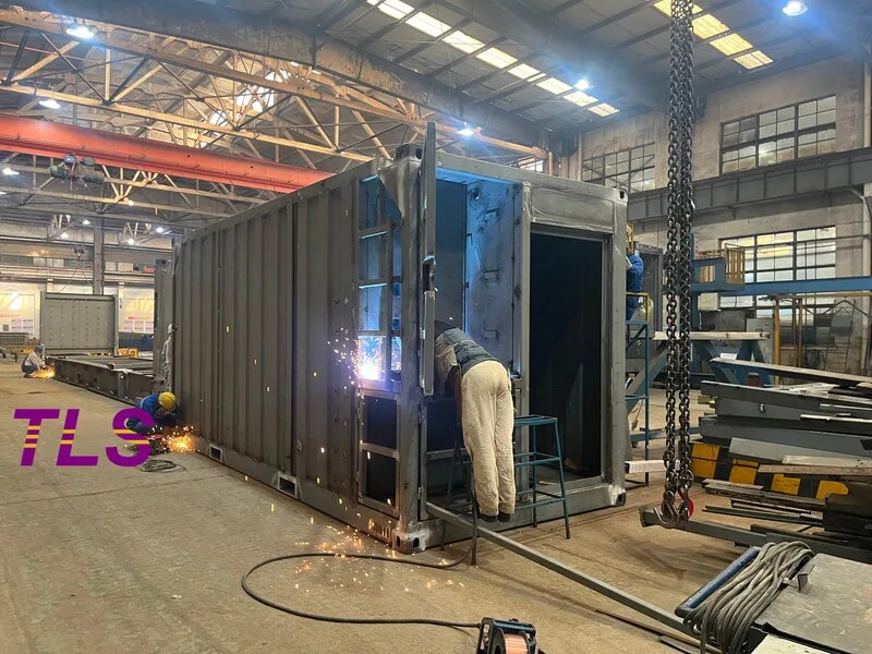
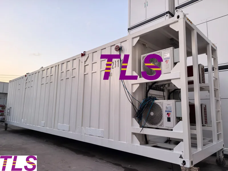
In modern offshore engineering and energy projects, special containers are no longer simple transportation units. They have become mobile fortresses carrying highly sensitive and high-value equipment worth millions of dollars.
Extreme offshore lifting conditions, violent wave-induced motion, and low-temperature brittleness in arctic environments all impose extreme demands on structural integrity.
At TLS Offshore Containers, advanced Finite Element Analysis (FEA) and virtual drop test simulations are integrated early in the design phase. By transforming physical structures into digital models, we can accurately predict stress concentration zones, optimize material usage, and eliminate structural fatigue risks before production begins.
This article explains how TLS applies FEA simulation technology to ensure absolute structural safety and full compliance with DNV 2.7-1 standards in harsh offshore environments.
Key Questions This Article Addresses:
1. What Is Finite Element Analysis (FEA) and Its Role in Container Design?
Finite Element Analysis (FEA) is a numerical simulation method used to approximate the behavior of real-world physical systems under various loads and conditions.
At TLS R&D centers, engineers convert complex 3D CAD models of customized containers into thousands of small elements. These elements are then analyzed under real-world offshore conditions, including:
Before a single steel plate is cut, we already understand how the structure will perform in offshore environments.
2. Offshore Lifting: Structural Response Under Dynamic Impact
One of the most critical risks in offshore operations is offshore lifting (Offshore Lifting), where wave motion causes vessel instability and introduces dynamic amplification effects.
Key Engineering Focus Areas:
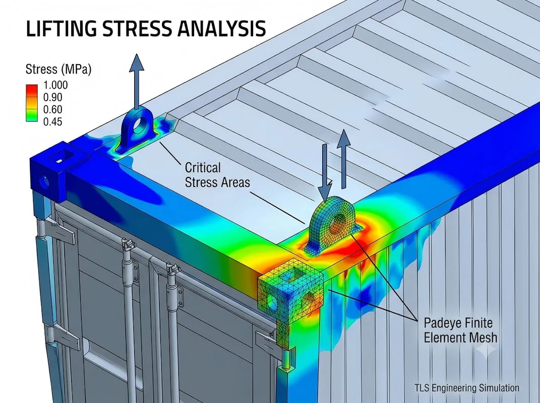
2.1 Padeyes and Corner Lifting Points
Padeyes and lifting lugs are the most critical load-bearing components.
Through FEA simulation, TLS evaluates multi-angle lifting conditions to ensure:
2.2 Frame Torsional Resistance Design
During offshore motion, containers experience twisting and shear forces.
FEA helps optimize:
3. Virtual Drop Test: Final Safety Barrier for Explosion-Proof and Energy Containers
For TLS Energy Storage Systems (ESS) and Zone 1 / Zone 2 hazardous area containers, internal equipment such as battery systems and control units are highly sensitive to impact.
3.1 Nonlinear Dynamic Drop Simulation
FEA is used to simulate extreme drop scenarios based on DNV requirements, including:
3.2 Transient Dynamic Analysis
The simulation captures energy transfer within milliseconds after impact.
The goal is to ensure:
4. Business Value: How FEA Improves ROI for Customers
For procurement and project stakeholders, FEA is not just engineering validation—it is a direct driver of cost efficiency and risk reduction.
4.1 Reduced Project Delivery Time
Traditional approach:
4.2 Optimized Structural Weight and Logistics Cost
Traditional approach:
4.3 First-Time Certification Success
Traditional approach:
Conclusion
By integrating Finite Element Analysis (FEA) throughout the entire product development lifecycle, TLS effectively eliminates uncertainty before manufacturing begins.
Key Takeaways:
Keywords :#Finite Element Analysis container design, #Offshore lifting structural analysis, #DNV 2.7-1 compliance containers, #Special offshore containers engineering, #Explosion-proof container design simulation, #Energy storage container FEA analysis, #Virtual drop test simulation container, #Structural optimization offshore containers, #TLS offshore container engineering solutions, #Hazardous area container structural safety
Extreme offshore lifting conditions, violent wave-induced motion, and low-temperature brittleness in arctic environments all impose extreme demands on structural integrity.
At TLS Offshore Containers, advanced Finite Element Analysis (FEA) and virtual drop test simulations are integrated early in the design phase. By transforming physical structures into digital models, we can accurately predict stress concentration zones, optimize material usage, and eliminate structural fatigue risks before production begins.
This article explains how TLS applies FEA simulation technology to ensure absolute structural safety and full compliance with DNV 2.7-1 standards in harsh offshore environments.
Key Questions This Article Addresses:
- What is Finite Element Analysis (FEA) and how is it applied in special container design?
- How does FEA predict and mitigate structural risks during offshore lifting operations?
- How does TLS ensure safety for hazardous area containers through virtual drop test simulation?
- What cost and compliance advantages does FEA bring to customers?
1. What Is Finite Element Analysis (FEA) and Its Role in Container Design?
Finite Element Analysis (FEA) is a numerical simulation method used to approximate the behavior of real-world physical systems under various loads and conditions.
At TLS R&D centers, engineers convert complex 3D CAD models of customized containers into thousands of small elements. These elements are then analyzed under real-world offshore conditions, including:
- Gravity loads
- Wind loads
- Lifting forces
- Temperature effects
- Stress distribution (Stress)
- Deformation behavior (Displacement)
Before a single steel plate is cut, we already understand how the structure will perform in offshore environments.
2. Offshore Lifting: Structural Response Under Dynamic Impact
One of the most critical risks in offshore operations is offshore lifting (Offshore Lifting), where wave motion causes vessel instability and introduces dynamic amplification effects.
Key Engineering Focus Areas:
2.1 Padeyes and Corner Lifting Points
Padeyes and lifting lugs are the most critical load-bearing components.
Through FEA simulation, TLS evaluates multi-angle lifting conditions to ensure:
- Von Mises stress remains well below material yield strength
- Welded joints maintain structural integrity under extreme loads
2.2 Frame Torsional Resistance Design
During offshore motion, containers experience twisting and shear forces.
FEA helps optimize:
- Corner post geometry
- Upper frame reinforcement structure
3. Virtual Drop Test: Final Safety Barrier for Explosion-Proof and Energy Containers
For TLS Energy Storage Systems (ESS) and Zone 1 / Zone 2 hazardous area containers, internal equipment such as battery systems and control units are highly sensitive to impact.
3.1 Nonlinear Dynamic Drop Simulation
FEA is used to simulate extreme drop scenarios based on DNV requirements, including:
- Corner drop impact
- Edge drop impact
- Flat surface impact
3.2 Transient Dynamic Analysis
The simulation captures energy transfer within milliseconds after impact.
The goal is to ensure:
- External steel structure absorbs most impact energy through controlled plastic deformation
- Internal equipment compartments remain nearly deformation-free
- Explosion-proof sealing integrity is maintained
- Battery thermal runaway risk is eliminated
4. Business Value: How FEA Improves ROI for Customers
For procurement and project stakeholders, FEA is not just engineering validation—it is a direct driver of cost efficiency and risk reduction.
4.1 Reduced Project Delivery Time
Traditional approach:
- Multiple physical prototypes
- Repeated testing and redesign cycles
- Long engineering lead time
- Parallel digital engineering workflow
- No need for repeated physical iteration
- Over 30% reduction in design and delivery time
4.2 Optimized Structural Weight and Logistics Cost
Traditional approach:
- Over-designed structures for safety margin
- Excess steel usage increases weight
- Higher transportation and lifting costs
- Topology optimization
- Precise material distribution based on stress analysis
- Significant reduction in structural weight and logistics expenses
4.3 First-Time Certification Success
Traditional approach:
- Trial-and-error certification submissions
- Risk of non-compliance and project delays
- Fully digital pre-validation based on DNV 2.7-1 and EN 12079 standards
- Accurate boundary condition modeling
- High probability of first-time approval by classification societies
Conclusion
By integrating Finite Element Analysis (FEA) throughout the entire product development lifecycle, TLS effectively eliminates uncertainty before manufacturing begins.
Key Takeaways:
- Technical Core: FEA enables precise prediction of structural stress, stiffness, and fatigue performance through digital modeling.
- Critical Applications: Offshore lifting load analysis and impact resistance validation for explosion-proof and energy storage containers.
- Customer Value: Shorter delivery cycles, optimized structural weight for reduced logistics cost, and improved compliance success rates with international standards such as DNV 2.7-1.
Keywords :#Finite Element Analysis container design, #Offshore lifting structural analysis, #DNV 2.7-1 compliance containers, #Special offshore containers engineering, #Explosion-proof container design simulation, #Energy storage container FEA analysis, #Virtual drop test simulation container, #Structural optimization offshore containers, #TLS offshore container engineering solutions, #Hazardous area container structural safety
Written by Snowy
- Published on
There's a number the industry rarely says out loud: roughly 90% of liquid cooling failures trace back to the piping system. Not the CDU. Not the cold plates. The pipes, fittings, and the connections between them. Understanding why — and how the same failure modes migrate into Battery Energy Storage System (BESS) thermal management — is essential for anyone designing infrastructure where heat removal is mission-critical.
The Hidden Failure Chain in Liquid Cooling
Most cooling incidents don't announce themselves dramatically. They begin quietly: a fitting that wasn't torqued to spec, a weld with a hairline defect, a pocket of trapped air causing a water hammer event at 2 AM. By the time the leak is visible, a cascade is already in motion — downtime, equipment damage, and replacement costs that dwarf what proper design would have cost.
The root cause is almost always a gap between disciplines. HVAC engineers understand fluid dynamics but not the uptime requirements of critical infrastructure. Data center operators know their SLAs but not pipe schedules. BESS integrators, under pressure to hit energy density targets, often treat thermal management as a secondary system — until it isn't.
Material Selection: Getting the Foundation Right
Three material families dominate liquid cooling piping, each with a specific role:
Stainless steel (304/316L) is the backbone of primary circuits. With a service life exceeding 20 years and excellent corrosion resistance, 316L is the preferred choice where chloride exposure is a risk — common in coastal BESS installations. The trade-off is weight and cost.
Specialty thermoplastic pipe (PP-R) handles secondary, low-pressure circuits effectively. It's roughly one-third to one-half the cost of stainless, installs quickly via heat fusion, and presents low flow resistance. But it's pressure-limited (generally PN ≤ 2.0 MPa) and degrades above 70°C — a constraint that matters in high-density BESS configurations where ambient temperatures inside enclosures can spike.
Flexible braided hose absorbs vibration and compensates for thermal expansion at equipment connection points. Quality matters enormously here; substandard liners develop microcracks within months.
A reliable combination: 316L stainless for main runs, PP-R for branch circuits, and stainless braided flex at CDU and battery module interfaces.
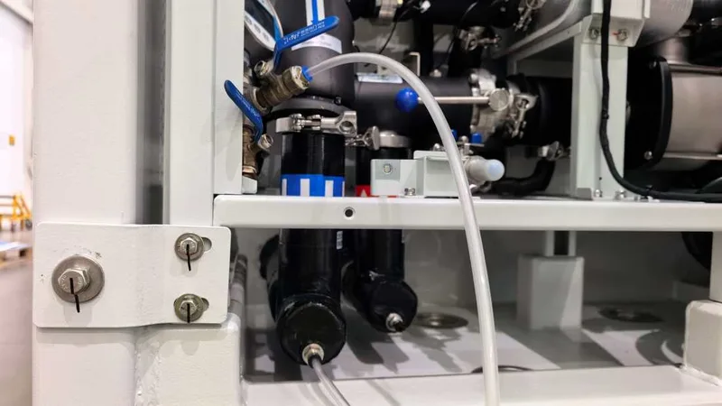
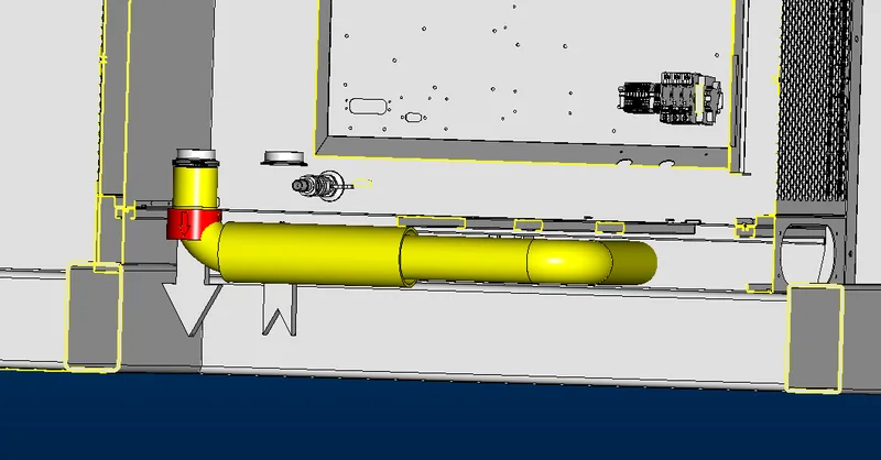
Fittings Are Where Leaks Live
Over 60% of piping leaks originate at joints. Compression fittings require torque wrenches and manufacturer-specified values — under-tightened fittings seep, over-tightened ones deform. Flanged connections above DN50 need EPDM gaskets (rated –40°C to +150°C) tightened in a cross-pattern across three passes. Field welds demand 100% radiographic or dye-penetrant inspection on critical joints; weld quality is highly dependent on the welder, ambient wind, and humidity at the time of execution.
Sizing, Slope, and the Air Problem
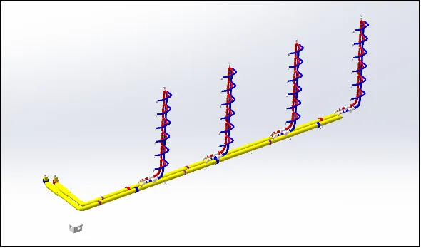
Flow velocity dictates both efficiency and longevity. In primary circuits (CDU to dry cooler), target 1.5–3.0 m/s. Secondary circuits (CDU to rack or battery module) run better at 0.5–1.5 m/s. A useful first estimate: pipe diameter (mm) ≈ √(flow rate in L/min ÷ 0.3).
Trapped air is the silent degrader. Bubbles reduce heat transfer, cause flow imbalance, and damage pump impellers through cavitation. Every high point in the circuit needs an automatic air vent. Pipe runs should slope upward at least 0.3% in the direction of flow. At system commissioning, fill at 30% of design flow rate and hold for two to four hours before ramping up — rushing this step embeds micro-bubbles that are nearly impossible to purge later.
Applying This to BESS Thermal Management
Battery cells are far less forgiving than servers. A lithium-ion cell operating outside its thermal window — typically 15°C to 35°C — degrades faster, loses capacity, and in extreme cases enters thermal runaway. The TMS for a BESS is therefore not comfort infrastructure; it is a safety system.
Liquid cooling architectures for BESS fall into two main configurations: direct cold-plate cooling (coolant channels integrated into module housings) and indirect liquid cooling with a secondary glycol-water loop. The latter is more common at utility scale, using a circuit architecture nearly identical to data center liquid cooling — CDU-equivalent, distribution manifolds, and per-rack (per-module) supply and return.
Key BESS-specific TMS design considerations:
Periodically Inspection Protocol
Regardless of application — data center or BESS — the maintenance discipline is the same. Visually inspect all visible fittings for crystalline deposits or moisture. Check flexible hose for bulging or surface cracking, especially at attachment points. Confirm automatic air vents are cycling correctly. Log CDU inlet/outlet temperatures, flow rates, and pressures against baseline. Verify expansion tank levels. Listen to pumps for cavitation noise or bearing roughness. Test coolant conductivity and pH monthly.
Thermal management is not a set-and-forget system. The infrastructure that moves heat away from billions of dollars of batteries and compute deserves the same engineering rigor as the assets it protects.
The Hidden Failure Chain in Liquid Cooling
Most cooling incidents don't announce themselves dramatically. They begin quietly: a fitting that wasn't torqued to spec, a weld with a hairline defect, a pocket of trapped air causing a water hammer event at 2 AM. By the time the leak is visible, a cascade is already in motion — downtime, equipment damage, and replacement costs that dwarf what proper design would have cost.
The root cause is almost always a gap between disciplines. HVAC engineers understand fluid dynamics but not the uptime requirements of critical infrastructure. Data center operators know their SLAs but not pipe schedules. BESS integrators, under pressure to hit energy density targets, often treat thermal management as a secondary system — until it isn't.
Material Selection: Getting the Foundation Right
Three material families dominate liquid cooling piping, each with a specific role:
Stainless steel (304/316L) is the backbone of primary circuits. With a service life exceeding 20 years and excellent corrosion resistance, 316L is the preferred choice where chloride exposure is a risk — common in coastal BESS installations. The trade-off is weight and cost.
Specialty thermoplastic pipe (PP-R) handles secondary, low-pressure circuits effectively. It's roughly one-third to one-half the cost of stainless, installs quickly via heat fusion, and presents low flow resistance. But it's pressure-limited (generally PN ≤ 2.0 MPa) and degrades above 70°C — a constraint that matters in high-density BESS configurations where ambient temperatures inside enclosures can spike.
Flexible braided hose absorbs vibration and compensates for thermal expansion at equipment connection points. Quality matters enormously here; substandard liners develop microcracks within months.
A reliable combination: 316L stainless for main runs, PP-R for branch circuits, and stainless braided flex at CDU and battery module interfaces.
Fittings Are Where Leaks Live
Over 60% of piping leaks originate at joints. Compression fittings require torque wrenches and manufacturer-specified values — under-tightened fittings seep, over-tightened ones deform. Flanged connections above DN50 need EPDM gaskets (rated –40°C to +150°C) tightened in a cross-pattern across three passes. Field welds demand 100% radiographic or dye-penetrant inspection on critical joints; weld quality is highly dependent on the welder, ambient wind, and humidity at the time of execution.
Sizing, Slope, and the Air Problem
Flow velocity dictates both efficiency and longevity. In primary circuits (CDU to dry cooler), target 1.5–3.0 m/s. Secondary circuits (CDU to rack or battery module) run better at 0.5–1.5 m/s. A useful first estimate: pipe diameter (mm) ≈ √(flow rate in L/min ÷ 0.3).
Trapped air is the silent degrader. Bubbles reduce heat transfer, cause flow imbalance, and damage pump impellers through cavitation. Every high point in the circuit needs an automatic air vent. Pipe runs should slope upward at least 0.3% in the direction of flow. At system commissioning, fill at 30% of design flow rate and hold for two to four hours before ramping up — rushing this step embeds micro-bubbles that are nearly impossible to purge later.
Applying This to BESS Thermal Management
Battery cells are far less forgiving than servers. A lithium-ion cell operating outside its thermal window — typically 15°C to 35°C — degrades faster, loses capacity, and in extreme cases enters thermal runaway. The TMS for a BESS is therefore not comfort infrastructure; it is a safety system.
Liquid cooling architectures for BESS fall into two main configurations: direct cold-plate cooling (coolant channels integrated into module housings) and indirect liquid cooling with a secondary glycol-water loop. The latter is more common at utility scale, using a circuit architecture nearly identical to data center liquid cooling — CDU-equivalent, distribution manifolds, and per-rack (per-module) supply and return.
Key BESS-specific TMS design considerations:
- Cell-level temperature uniformity matters more than average temperature. A ΔT above 5°C across a module accelerates imbalanced aging and capacity fade. Piping design must ensure balanced flow to every module — this requires careful manifold geometry and, in larger systems, pressure-independent control valves per branch.
- Freeze protection is non-negotiable for outdoor BESS enclosures. Glycol concentration must be sized for the site's design minimum ambient temperature, with a safety margin. Pipe routing within enclosures should minimize exposure to cold zones, and heat tracing may be required in extreme climates.
- Vibration isolation is more demanding than in static data center environments. BESS containers on skids or floating foundations experience movement; all module connections need flexible elements and adequate support spacing to prevent fatigue failure.
- Leak detection integration should be specified at the system level, not added as an afterthought. BESS enclosures typically have limited drainage paths; even a small leak can accumulate and create electrical hazards. Sensor strips beneath manifolds and at low points, tied to automatic shutoff valves, are standard practice in well-designed systems.
- CDU sizing follows the same logic as data center applications: total battery pack heat rejection capacity × 1.1–1.2 safety factor, with redundant pump sets (N+1 minimum) and dual CDU configurations for systems above 1 MWh.
Periodically Inspection Protocol
Regardless of application — data center or BESS — the maintenance discipline is the same. Visually inspect all visible fittings for crystalline deposits or moisture. Check flexible hose for bulging or surface cracking, especially at attachment points. Confirm automatic air vents are cycling correctly. Log CDU inlet/outlet temperatures, flow rates, and pressures against baseline. Verify expansion tank levels. Listen to pumps for cavitation noise or bearing roughness. Test coolant conductivity and pH monthly.
Thermal management is not a set-and-forget system. The infrastructure that moves heat away from billions of dollars of batteries and compute deserves the same engineering rigor as the assets it protects.
- Published on
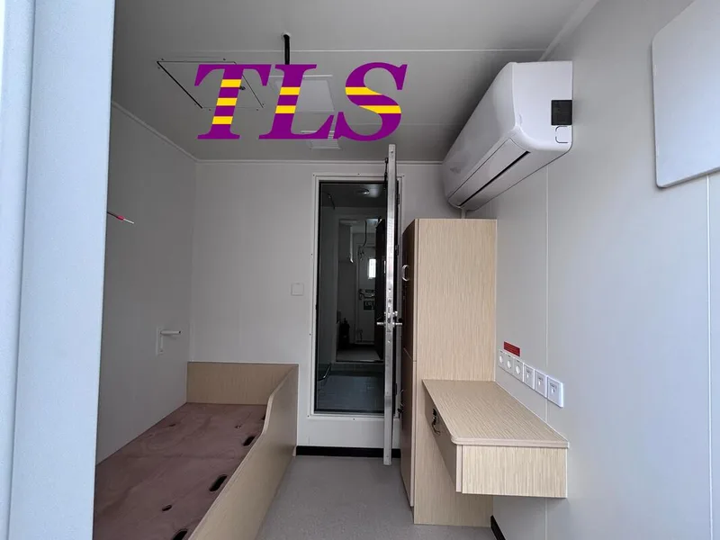
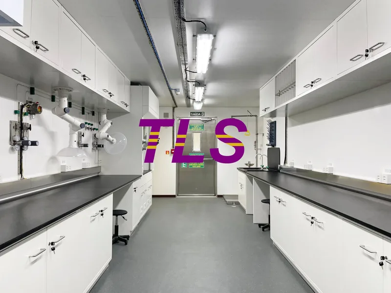
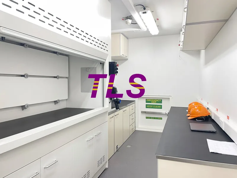
In industries such as oil and gas exploration, marine engineering, mining development, environmental monitoring, and industrial testing, an increasing number of laboratory and analytical activities are shifting from traditional fixed facilities to on-site, modular solutions. Laboratory Containers have become an important platform for conducting field testing, data analysis, and sample processing.
However, when selecting a laboratory container solution, many users face several practical questions:
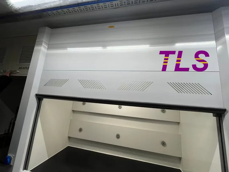
A Laboratory Container Is More Than Just a Container
Many people assume that a laboratory container is simply a shipping container with laboratory equipment installed inside.
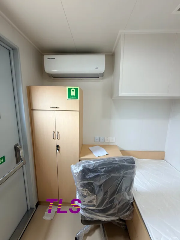
In reality, a complete laboratory container functions as a mobile laboratory environment that must simultaneously meet the requirements of equipment operation, personnel safety, and laboratory management.
1. Container Structure System
As the physical platform for laboratory equipment, the container structure must provide:
2. Power and Electrical Distribution System
Laboratory equipment often requires a highly stable power supply.
A laboratory container is typically equipped with:
3. Ventilation and Environmental Control System
Environmental stability directly affects testing accuracy and data reliability.
Depending on project requirements, a laboratory container may be equipped with:
4. Safety Monitoring System
For applications involving hazardous gases or specialized laboratory processes, the following systems are commonly integrated:
How Does a Laboratory Container Work?
The primary objective of a laboratory container is to create a stable and controlled operating environment for laboratory equipment.
Its typical operating process includes the following steps:
Step 1: Parameter Configuration
Operators set the required operating conditions, including:
Step 2: Environmental Control
The HVAC, ventilation, and pressure control systems automatically operate based on the preset values to maintain a stable laboratory environment.
Step 3: Testing and Monitoring
Once the laboratory equipment begins operating, various sensors continuously monitor:
Step 4: Data Collection and Recording
Test data can be monitored and stored in real time through:
Step 5: Alarm and System Interlock
If abnormal conditions occur, the system can automatically:
What Standards and Certifications Must a Laboratory Container Meet?
For industrial applications, laboratory containers must comply not only with functional requirements but also with relevant regulations and industry standards.
Common standards include:
1. Quality Management
ISO 9001, which ensures quality control throughout the design and manufacturing process.
2. Electrical and Equipment Safety
CE, UL, and relevant IEC standards, which verify electrical safety and regulatory compliance.
3. Hazardous Area Applications
When a laboratory container is installed in hazardous locations, explosion protection requirements such as the following may apply: ATEX& IECEx
4. Offshore and Marine Projects
For offshore laboratory containers, additional structural and transportation certifications may be required, including:DNV 2.7-1 & EN 12079& CSC
What Applications Are Laboratory Containers Suitable For?
As demand for on-site testing continues to increase, laboratory containers are now widely used across multiple industries.
Conclusion: What Should You Focus on When Selecting a Laboratory Container?
For field testing and laboratory applications, a laboratory container is not merely a space for equipment installation. It is a critical platform that supports testing accuracy, operational safety, and overall efficiency.
When evaluating a laboratory container solution, it is recommended to focus on the following factors:
The value of a laboratory container extends beyond housing laboratory equipment. Its true purpose is to provide a safe, stable, and sustainable working environment for on-site testing and analysis. For projects that increasingly rely on real-time data and rapid decision-making, a properly designed laboratory container can significantly improve operational efficiency and data reliability.
Please download the Laboratory container brochure for reference.
Keywords:#Laboratory Container, #Containerized Laboratory, #Mobile Laboratory Container, #Offshore Laboratory Container, #Modular Laboratory Solution, #Field Testing Laboratory, #Hazardous Area Laboratory Container, #Environmental Monitoring Laboratory
However, when selecting a laboratory container solution, many users face several practical questions:
- What are the core systems that make up a laboratory container?
- How can laboratory equipment operate reliably in harsh environments?
- What certifications and safety standards must a laboratory container meet?
- How should different projects choose the most suitable laboratory container solution?
A Laboratory Container Is More Than Just a Container
Many people assume that a laboratory container is simply a shipping container with laboratory equipment installed inside.
In reality, a complete laboratory container functions as a mobile laboratory environment that must simultaneously meet the requirements of equipment operation, personnel safety, and laboratory management.
1. Container Structure System
As the physical platform for laboratory equipment, the container structure must provide:
- Sufficient structural strength
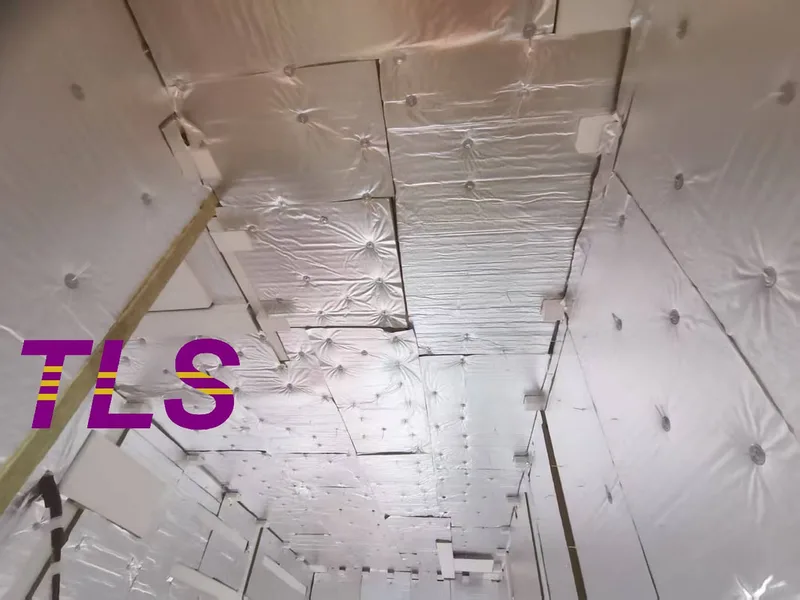
- Effective thermal insulation
- Corrosion resistance
- Long-term transportation and lifting capability
2. Power and Electrical Distribution System
Laboratory equipment often requires a highly stable power supply.
A laboratory container is typically equipped with:
- l Main power distribution system
- l Grounding system
- l Emergency power connection interface
3. Ventilation and Environmental Control System
Environmental stability directly affects testing accuracy and data reliability.
Depending on project requirements, a laboratory container may be equipped with:
- HVAC air conditioning system
- Fresh air system
- Exhaust ventilation system
- Positive pressure system
- Negative pressure system
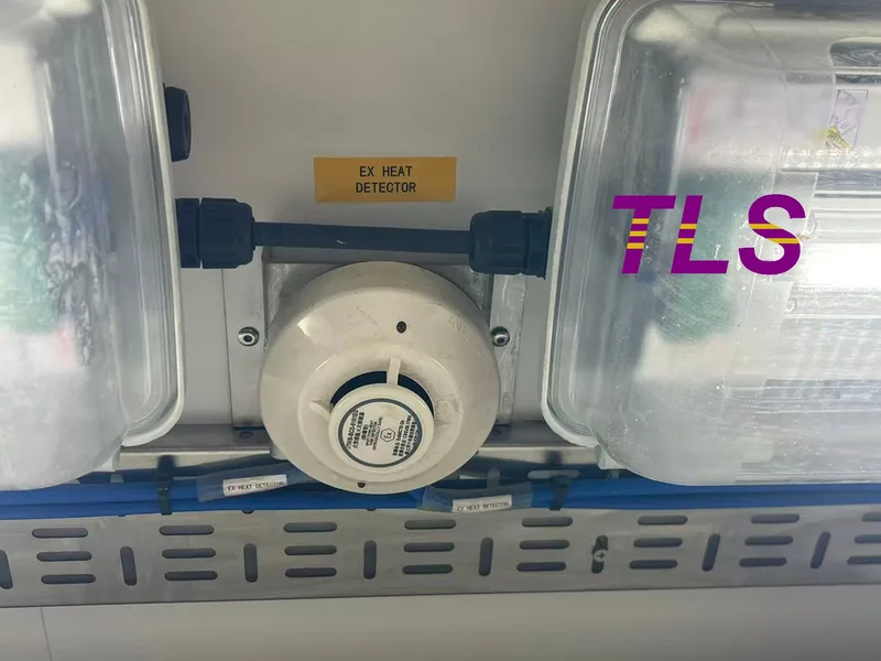
4. Safety Monitoring System
For applications involving hazardous gases or specialized laboratory processes, the following systems are commonly integrated:
- Combustible gas detectors
- H₂S detectors
- Smoke detectors
- Fire alarm systems
- Emergency Shutdown (ESD) systems
How Does a Laboratory Container Work?
The primary objective of a laboratory container is to create a stable and controlled operating environment for laboratory equipment.
Its typical operating process includes the following steps:
Step 1: Parameter Configuration
Operators set the required operating conditions, including:
- Temperature
- Humidity
- Ventilation rate
- Pressure conditions
Step 2: Environmental Control
The HVAC, ventilation, and pressure control systems automatically operate based on the preset values to maintain a stable laboratory environment.
Step 3: Testing and Monitoring
Once the laboratory equipment begins operating, various sensors continuously monitor:
- Temperature
- Pressure
- Gas concentration
- Equipment status
Step 4: Data Collection and Recording
Test data can be monitored and stored in real time through:
- PLC systems
- Industrial computers
- SCADA systems
Step 5: Alarm and System Interlock
If abnormal conditions occur, the system can automatically:
- Activate audible and visual alarms
- Start emergency ventilation
- Shut down designated equipment
What Standards and Certifications Must a Laboratory Container Meet?
For industrial applications, laboratory containers must comply not only with functional requirements but also with relevant regulations and industry standards.
Common standards include:
1. Quality Management
ISO 9001, which ensures quality control throughout the design and manufacturing process.
2. Electrical and Equipment Safety
CE, UL, and relevant IEC standards, which verify electrical safety and regulatory compliance.
3. Hazardous Area Applications
When a laboratory container is installed in hazardous locations, explosion protection requirements such as the following may apply: ATEX& IECEx
4. Offshore and Marine Projects
For offshore laboratory containers, additional structural and transportation certifications may be required, including:DNV 2.7-1 & EN 12079& CSC
What Applications Are Laboratory Containers Suitable For?
As demand for on-site testing continues to increase, laboratory containers are now widely used across multiple industries.
- Oil and Gas Industry
- Marine Engineering
- Mining and Metallurgy
- Environmental Monitoring
Conclusion: What Should You Focus on When Selecting a Laboratory Container?
For field testing and laboratory applications, a laboratory container is not merely a space for equipment installation. It is a critical platform that supports testing accuracy, operational safety, and overall efficiency.
When evaluating a laboratory container solution, it is recommended to focus on the following factors:
- Environmental Control Capability
- Safety System Configuration
- Certification and Compliance
- Customization Capability
The value of a laboratory container extends beyond housing laboratory equipment. Its true purpose is to provide a safe, stable, and sustainable working environment for on-site testing and analysis. For projects that increasingly rely on real-time data and rapid decision-making, a properly designed laboratory container can significantly improve operational efficiency and data reliability.
Please download the Laboratory container brochure for reference.
Keywords:#Laboratory Container, #Containerized Laboratory, #Mobile Laboratory Container, #Offshore Laboratory Container, #Modular Laboratory Solution, #Field Testing Laboratory, #Hazardous Area Laboratory Container, #Environmental Monitoring Laboratory
Written by Snowy
- Published on
Abstract : With the rapid global deployment of energy storage projects, battery containers have evolved from simple “structural enclosures” into critical components that directly impact system safety, delivery efficiency, and lifecycle cost. However, in real engineering projects, users often face several key questions:
This article addresses these questions from a full project delivery perspective. It breaks down six essential capabilities of battery containers—transport adaptability, environmental protection, thermal management, modular integration, customization flexibility, and maintenance friendliness—to help users build a clearer technical evaluation framework when selecting energy storage container solutions.
1. Transport Adaptability: Ensuring Safe Delivery to Site
Battery containers must pass through multiple stages before commissioning:
TLS designs focus on:
2. Environmental Protection: Adapting to Multi-Climate Deployment
Energy storage systems are often deployed in harsh environments such as:
TLS engineering focuses on:
Anti-corrosion system
3. Thermal Management: A Key Factor for Battery Lifespan
Battery performance is highly dependent on temperature stability.
Key challenges include:
Core idea: not adapting to the environment, but actively controlling it.
4. Modular Integration Capability: Driving Project Delivery Efficiency
Different projects require different levels of integration and delivery speed.
TLS offers three typical configurations:
Empty container solution
5. Customization Capability: Meeting Diverse Engineering Standards
Energy storage projects vary significantly across regions and clients, including:
Conclusion: Battery Containers Are the Core Enabler of System Stability
In energy storage systems, battery containers are not just structural enclosures—they are the foundation of stable system operation.
When evaluating solutions, six key dimensions should be prioritized:
1. Transport Safety
Ability to withstand full logistics and lifting processes
2. Environmental Adaptability
Performance under multi-climate and corrosive conditions
3. Thermal Management
Stable and reliable temperature control capability
4. Integration Flexibility
Support for multiple delivery models
5. Customization Capability
Compliance with diverse engineering standards
Through system-level engineering design, TLS upgrades battery containers from “structural enclosures” into “controlled operational platforms”, providing a more reliable foundation for utility-scale, wind, solar, and commercial energy storage projects.
Regarding the Battery Energy Storage System (BESS) container, please download Energy Storage System (ESS) Containers brochure for reference.
Keywords: #Energy Storage Container, #BESS Container Design, #Battery Energy Storage System,#Containerized Energy Storage , #Battery Container Integration, #Energy Storage Container Manufacturer,#Thermal Management for Battery Containers, #Custom Battery Container Solutions,#Utility Scale Energy Storage Projects
- How can battery containers withstand complex transportation and lifting conditions?
- How can stable operation be ensured under different climate and extreme environments?
- What level of modular integration is required to match different project schedules?
- How can standardization and customization be balanced in engineering practice?
This article addresses these questions from a full project delivery perspective. It breaks down six essential capabilities of battery containers—transport adaptability, environmental protection, thermal management, modular integration, customization flexibility, and maintenance friendliness—to help users build a clearer technical evaluation framework when selecting energy storage container solutions.
1. Transport Adaptability: Ensuring Safe Delivery to Site
Battery containers must pass through multiple stages before commissioning:
- Factory dispatch and loading
- Long-distance road transportation
- Sea freight and container handling
- On-site lifting and installation
TLS designs focus on:
- ISO-standard container dimension compatibility
- Reinforced base steel structure
- Optimized lifting point load distribution
- Vibration and shock resistance design
2. Environmental Protection: Adapting to Multi-Climate Deployment
Energy storage systems are often deployed in harsh environments such as:
- Coastal high-salt corrosion zones
- Desert high-temperature and dusty areas
- Tropical high-humidity regions
- Inland regions with extreme temperature differences
TLS engineering focuses on:
Anti-corrosion system
- ISO 12944 C4 / C5 coating compliance
- Multi-layer industrial coating system
- Optimized for salt spray and humidity resistance
- IP55 or higher structural protection
- Dustproof, waterproof, and moisture-resistant design
- Condensation drainage design
- Optimized airflow routing
- Reinforced sealing structure
3. Thermal Management: A Key Factor for Battery Lifespan
Battery performance is highly dependent on temperature stability.
Key challenges include:
- Thermal runaway risk at high temperatures
- Reduced performance in low temperatures
- Uneven internal temperature distribution
- Air-cooling integration
- Liquid-cooling interface pre-design
- Hybrid thermal control systems
- Heating and dehumidification systems
Core idea: not adapting to the environment, but actively controlling it.
4. Modular Integration Capability: Driving Project Delivery Efficiency
Different projects require different levels of integration and delivery speed.
TLS offers three typical configurations:
Empty container solution
- Structural container with interfaces only
- System integration completed by customer
- Suitable for highly customized projects
- Pre-installed structural components (racks, cable trays, etc.)
- Reduced on-site installation workload
- Suitable for standardized projects
- Battery, electrical, fire protection, and thermal systems pre-installed and tested
- Up to 90% factory integration
- Suitable for fast-track deployment projects
5. Customization Capability: Meeting Diverse Engineering Standards
Energy storage projects vary significantly across regions and clients, including:
- Electrical standards
- Fire safety regulations
- Communication protocols
- Interface requirements
- Structural and appearance specifications
- Electrical system configuration adjustments
- Compartment layout optimization
- Wiring and interface design customization
- Exterior coating and branding customization
Conclusion: Battery Containers Are the Core Enabler of System Stability
In energy storage systems, battery containers are not just structural enclosures—they are the foundation of stable system operation.
When evaluating solutions, six key dimensions should be prioritized:
1. Transport Safety
Ability to withstand full logistics and lifting processes
2. Environmental Adaptability
Performance under multi-climate and corrosive conditions
3. Thermal Management
Stable and reliable temperature control capability
4. Integration Flexibility
Support for multiple delivery models
5. Customization Capability
Compliance with diverse engineering standards
Through system-level engineering design, TLS upgrades battery containers from “structural enclosures” into “controlled operational platforms”, providing a more reliable foundation for utility-scale, wind, solar, and commercial energy storage projects.
Regarding the Battery Energy Storage System (BESS) container, please download Energy Storage System (ESS) Containers brochure for reference.
Keywords: #Energy Storage Container, #BESS Container Design, #Battery Energy Storage System,#Containerized Energy Storage , #Battery Container Integration, #Energy Storage Container Manufacturer,#Thermal Management for Battery Containers, #Custom Battery Container Solutions,#Utility Scale Energy Storage Projects
Written by Snowy
- Published on
Overview & Quick Answers
TLS Negative Pressure Containers provide mobile, containment-safe environments for high-stakes medical, research, and industrial sites. By maintaining an internal vacuum, these units guarantee zero outward contamination, even in extreme climates.
Key Questions Answered in this Article:
The Physics of Containment: Why Negative Pressure Matters
In high-stakes environments—ranging from infectious disease isolation to heavy industrial production—the smallest leak can lead to catastrophic safety failures. Harmful gases, microscopic dust, and volatile biological agents pose constant risks to personnel and local ecosystems.
TLS Negative Pressure Containers solve this by manipulating atmospheric physics. By keeping internal air pressure consistently lower than the external environment, the system creates a continuous inward airflow. Because air naturally moves from high to low pressure, air is constantly drawn into the container, ensuring that no contaminated particles can escape through doors, vents, or minor seal imperfections.
Core Pillars of the TLS Engineering System
The reliability of a TLS container rests on three fundamental engineering principles:
Comparative Performance: TLS vs. Traditional Shelters
When deploying containment units in the field, engineering differences directly impact operational success rates. Industry data highlights why standard temporary shelters fail where TLS containers succeed:
General Lessons from Past Containment Failures
A review of historical field containment failures reveals two major vulnerabilities: structural warping under extreme weather and delayed alarm response times. Traditional soft-walled or non-rigid structures frequently fail when external wind loads alter internal pressure dynamics. Furthermore, systems lacking second-by-second sensor tracking often experience containment breaches long before personnel are alerted. TLS containers directly address these lessons by utilizing rigid, weather-resistant steel and instant-trigger smart alarms.
The Bottom Line: The Mobility of Safety
The true value of a TLS Negative Pressure Container is its ability to bring a high-level laboratory or clean industrial environment directly to the site of a problem. By protecting people, equipment, and the environment simultaneously, these units represent the modern gold standard in mobile containment technology.
Key Takeaways
TLS Offshore Containers / TLS Energy is a global supplier of standard and customised containerised solutions.
Wherever you are in the world, TLS can help you. Please contact us.
Please download the Laboratory container brochure for reference.
Keywords: #Negative pressure container, #Mobile containment unit, #Hazardous materials isolation, #Airflow pressure differential, #Mobile cleanroom technology, #Precision exhaust management, #Laboratory safety, #Environmental isolation shelter, #Real-time pressure monitoring
TLS Negative Pressure Containers provide mobile, containment-safe environments for high-stakes medical, research, and industrial sites. By maintaining an internal vacuum, these units guarantee zero outward contamination, even in extreme climates.
Key Questions Answered in this Article:
- How do TLS negative-pressure containers prevent hazardous leaks? (Through precision exhaust management and a controlled inward airflow differential).
- What makes TLS units superior to traditional temporary containment shelters? (Weather-resistant steel construction, real-time sensor feedback, and predictable climate stability).
- Where are these containers most effectively deployed? (Offshore platforms, desert environments, infectious disease zones, and high-precision field labs).
The Physics of Containment: Why Negative Pressure Matters
In high-stakes environments—ranging from infectious disease isolation to heavy industrial production—the smallest leak can lead to catastrophic safety failures. Harmful gases, microscopic dust, and volatile biological agents pose constant risks to personnel and local ecosystems.
TLS Negative Pressure Containers solve this by manipulating atmospheric physics. By keeping internal air pressure consistently lower than the external environment, the system creates a continuous inward airflow. Because air naturally moves from high to low pressure, air is constantly drawn into the container, ensuring that no contaminated particles can escape through doors, vents, or minor seal imperfections.
Core Pillars of the TLS Engineering System
The reliability of a TLS container rests on three fundamental engineering principles:
- Precision Exhaust Management: A continuous, high-capacity exhaust system maintains a constant vacuum effect, preventing the outward migration of hazardous particles.
- Intelligent Airflow Direction: Designated inlets and managed pathways ensure fresh air enters predictably, creating a safe breathing environment for operators without breaking the containment shield.
- Real-Time Monitoring and Alarms: Integrated pressure sensors track the internal state every second. Immediate visual and audible alarms trigger if pressure fluctuates due to power surges or unsealed doors.
Comparative Performance: TLS vs. Traditional Shelters
When deploying containment units in the field, engineering differences directly impact operational success rates. Industry data highlights why standard temporary shelters fail where TLS containers succeed:
- Containment Efficiency: Standard PVC/fabric temporary shelters experience up to a 15% containment degradation over time due to material wear and joint leaks. TLS-engineered steel units maintain 100% containment integrity via continuous negative pressure.
- Climate Resilience: Traditional shelters show a significant drop in internal climate stability when ambient temperatures exceed 40°C or drop below 0°C. TLS units maintain a stable internal climate regardless of external chaos, including corrosive salt spray and desert sandstorms.
- Operational Downtime: Standard shelters suffer frequent micro-downtime due to dust settling on sensitive equipment or lingering odors. TLS units offer 100% predictable ventilation, eliminating environmental wildcards.
General Lessons from Past Containment Failures
A review of historical field containment failures reveals two major vulnerabilities: structural warping under extreme weather and delayed alarm response times. Traditional soft-walled or non-rigid structures frequently fail when external wind loads alter internal pressure dynamics. Furthermore, systems lacking second-by-second sensor tracking often experience containment breaches long before personnel are alerted. TLS containers directly address these lessons by utilizing rigid, weather-resistant steel and instant-trigger smart alarms.
The Bottom Line: The Mobility of Safety
The true value of a TLS Negative Pressure Container is its ability to bring a high-level laboratory or clean industrial environment directly to the site of a problem. By protecting people, equipment, and the environment simultaneously, these units represent the modern gold standard in mobile containment technology.
Key Takeaways
- The Core Mechanism: Negative pressure forces air to flow exclusively inward, making it physically impossible for airborne contaminants to escape the container.
- The Three Safeguards: Continuous vacuum exhaust, directional fresh air pathways, and second-by-second sensor monitoring guarantee operational safety.
- The Environmental Advantage: Weather-resistant steel construction protects internal processes from extreme humidity, sand, and corrosive salt spray.
- The Primary Benefit: It replaces the unpredictable "wildcards" of field research with a stable, predictable, and highly mobile cleanroom environment.
TLS Offshore Containers / TLS Energy is a global supplier of standard and customised containerised solutions.
Wherever you are in the world, TLS can help you. Please contact us.
Please download the Laboratory container brochure for reference.
Keywords: #Negative pressure container, #Mobile containment unit, #Hazardous materials isolation, #Airflow pressure differential, #Mobile cleanroom technology, #Precision exhaust management, #Laboratory safety, #Environmental isolation shelter, #Real-time pressure monitoring
Written by Oliver
- Published on
Overview
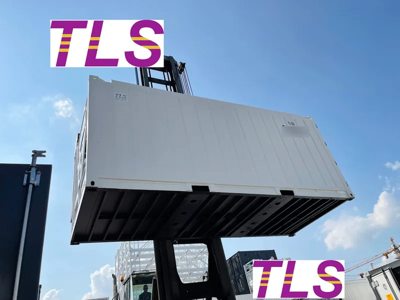
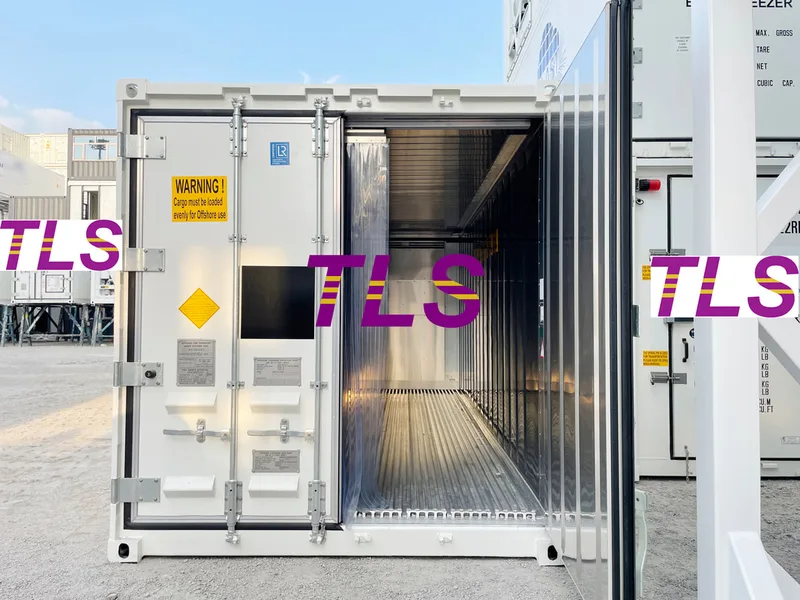
Offshore cold chain logistics require extreme environmental resilience and strict climate control to protect high-stakes cargo. TLS Offshore Reefer Containers solve these challenges by integrating high-density polyurethane insulation (50mm–120mm) and eco-friendly refrigerants (CO₂ / NH₃) with automated IoT tracking. This engineering stabilizes internal climates to within ±0.5°C, mitigating the structural, thermal, and regulatory risks typical of deep-sea and platform transits.
Core Questions Answered in This Article
The Cold Chain Challenge: Why Standard Units Fail
1. The Critical Need for Offshore Precision
Transporting perishable food supplies, fresh seafood, and critical pharmaceuticals to remote marine platforms presents environmental obstacles that standard logistics equipment cannot withstand. In offshore operations, a minor temperature fluctuation can compromise entire shipments, threatening worker safety and operational compliance.
2. Core Parameters for Marine Cargo Security
To safeguard product integrity from port to platform, offshore reefers must satisfy strict performance baselines:
3. Engineering for Extremes: TLS Cold Chain Technology
Comparative Data and Strategic Lessons
1. Data-Backed Performance Validation
Field testing and operational metrics demonstrate the clear performance gap between specialized offshore reefers and standard logistics units:
2. Industry Lessons: The Cost of Cold Chain Failure
Past maritime logistics failures offer critical insights into the necessity of ruggedized equipment:
Summary and Key Takeaways
1. Equipment Reliability
2. Environmental & Operational Intelligence
3. Risk Mitigation
TLS Offshore Containers / TLS Energy is a global supplier of standard and customised containerised solutions.
Wherever you are in the world, TLS can help you. Please contact us.
For any more information regarding Offshore Reefer container, ISO reefer container, please download offshore reefer container brochure for reference.
Keywords: #Offshore Reefer Containers, #Cold Chain Logistics, #Product Integrity, #IoT Monitoring, #Thermal Insulation, #Eco-Friendly Refrigerants, #Temperature Stability, #HACCP & GDP Compliance, #Marine Environment Resilience
Offshore cold chain logistics require extreme environmental resilience and strict climate control to protect high-stakes cargo. TLS Offshore Reefer Containers solve these challenges by integrating high-density polyurethane insulation (50mm–120mm) and eco-friendly refrigerants (CO₂ / NH₃) with automated IoT tracking. This engineering stabilizes internal climates to within ±0.5°C, mitigating the structural, thermal, and regulatory risks typical of deep-sea and platform transits.
Core Questions Answered in This Article
- Why do standard shipping containers fail in offshore cold chain logistics?
- How does TLS technology protect sensitive cargo against extreme marine environments?
- What role do automated monitoring and eco-friendly refrigerants play in modern offshore operations?
The Cold Chain Challenge: Why Standard Units Fail
1. The Critical Need for Offshore Precision
Transporting perishable food supplies, fresh seafood, and critical pharmaceuticals to remote marine platforms presents environmental obstacles that standard logistics equipment cannot withstand. In offshore operations, a minor temperature fluctuation can compromise entire shipments, threatening worker safety and operational compliance.
2. Core Parameters for Marine Cargo Security
To safeguard product integrity from port to platform, offshore reefers must satisfy strict performance baselines:
- Thermal Accuracy: Maintaining internal climates within a strict variance of ±0.5°C.
- Global Certifications: Aligning with international food safety standards like HACCP and pharmaceutical compliance frameworks, including Good Distribution Practice (GDP).
- Continuous Monitoring: Utilizing IoT telemetry to achieve end-to-end data visibility across long sea transits.
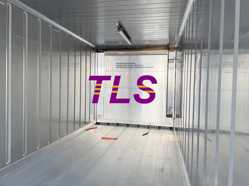
3. Engineering for Extremes: TLS Cold Chain Technology
- High-Performance Thermal Barriers
- Structural Integrity Against Mechanical Stress
- Sustainable and Smart Climate Systems
Comparative Data and Strategic Lessons
1. Data-Backed Performance Validation
Field testing and operational metrics demonstrate the clear performance gap between specialized offshore reefers and standard logistics units:
- Temperature Stability: Specialized reefers maintain a consistent ±0.5°C internal variance, whereas standard commercial reefers can experience fluctuations exceeding ±3.0°C under intense marine heat.
- Thermal Hold Times: High-density 120mm PU foam insulation extends the internal thermal safety window up to 4x longer during unexpected platform power outages compared to standard 40mm alternatives.
- Corrosion Lifecycle: Marine-grade protective coatings extend the operational life of the asset by over 200% in high-salinity environments compared to baseline commercial steel containers.
2. Industry Lessons: The Cost of Cold Chain Failure
Past maritime logistics failures offer critical insights into the necessity of ruggedized equipment:
- The Manual Inspection Blindspot: Relying on manual temperature logs instead of real-time IoT alerts historically led to delayed detection of cooling failures, resulting in total cargo loss before the vessel reached the platform.
- The Structural Vibration Oversight: Utilizing standard terrestrial container chassis in offshore environments frequently caused structural stress fractures and refrigerant line leaks due to continuous marine hull vibrations.
- The Insulation Breakdown Lesson: Insufficient insulation thickness caused persistent "hot spots" near outer container walls during equatorial transits, ruining sensitive pharmaceutical supplies while the central thermostat registered a false normal reading.
Summary and Key Takeaways
1. Equipment Reliability
- Specialized offshore reefers utilize 50mm to 120mm high-density PU foam to maintain a strict ±0.5°C climate variance.
- Heavy-duty structural reinforcement and anti-corrosive coatings protect units from high-impact crane lifts and saltwater degradation.
2. Environmental & Operational Intelligence
- Implementing CO₂ and NH₃ refrigerants reduces the carbon footprint and minimizes the electrical load on offshore vessels.
- Integrated IoT telemetry and predictive analytics replace manual checks, flagging performance anomalies automatically before cargo spoilage occurs.
3. Risk Mitigation
- Deploying purpose-built marine reefers addresses past industry failures tied to structural vibration leaks, manual tracking blindspots, and uneven insulation.
TLS Offshore Containers / TLS Energy is a global supplier of standard and customised containerised solutions.
Wherever you are in the world, TLS can help you. Please contact us.
For any more information regarding Offshore Reefer container, ISO reefer container, please download offshore reefer container brochure for reference.
Keywords: #Offshore Reefer Containers, #Cold Chain Logistics, #Product Integrity, #IoT Monitoring, #Thermal Insulation, #Eco-Friendly Refrigerants, #Temperature Stability, #HACCP & GDP Compliance, #Marine Environment Resilience
Written by Oliver
- Published on
Overview
Offshore energy operations face severe financial and safety risks from equipment failure in volatile marine environments. TLS Pressurized MCC (Motor Control Center) Shelters mitigate these risks by using positive-pressure technology and IEC60079-13 compliance to protect critical electrical infrastructure. This article evaluates how pressurized enclosures prevent Zone 2 explosions, analyzes the industry-wide failure points of standard containers, and outlines the long-term ROI of specialized marine engineering.
Key Questions Addressed in This Article
To help you navigate this guide, we directly answer the following critical industry questions:
1. Defining the Pressurized MCC Shelter: The Physics of Protection
A pressurized Motor Control Center (MCC) shelter is a specialized, climate-controlled enclosure engineered to house switchgear, motor starters, and complex control systems.
Unlike standard industrial containers, these units utilize advanced HVAC systems to maintain a continuous positive pressure environment. By keeping the internal air pressure slightly higher than the external atmosphere, the shelter creates a literal one-way aerodynamic barrier.
This barrier effectively blocks:
In Zone 2 hazardous locations, this mechanical separation is the primary line of defense against catastrophic short circuits and catastrophic arc-flash explosions.
2. Industry Benchmark: The Critical Role of IEC60079-13 Compliance
Safety in offshore environments is dictated by strict international legal frameworks. TLS shelters are engineered and certified in full accordance with the IEC60079-13 standard, which governs the protection of equipment in hazardous areas via pressurized rooms.
Compliance with IEC60079-13 is not a legal formality—it is a foundational safety guarantee. If an external flammable gas leak occurs on an offshore platform, the strict pressure thresholds maintained by the TLS shelter ensure that the internal electrical components are completely isolated. Consequently, they cannot act as an ignition source, effectively securing the platform and protecting human life.
3. Industry Comparison: Standard Containers vs. TLS Pressurized Shelters
Deploying inadequate infrastructure offshore leads to rapid, costly operational failures. Reviewing common industry blind spots highlights the necessity of specialized engineering.
The Vulnerability of Generic Enclosures
Historically, the use of standard ISO containers or basic modified enclosures offshore has led to systemic reliability issues. Without positive pressure, standard seals inevitably degrade under constant marine exposure, allowing moisture, salt spray, and humidity to penetrate the hull. This ingress causes rapid pitting corrosion on switchgear components, leading to moisture-induced short circuits. Because unplanned downtime on an offshore rig can cost hundreds of thousands of dollars per day, these avoidable equipment failures represent an unsustainable financial and safety liability for operators.
The Solution: The TLS Performance Advantage
By contrast, TLS Pressurized Shelters are built from the ground up to endure the harshest elements through advanced material science:
4. Maximizing ROI: Operational Efficiency and Customization
While safety is the primary engineering driver, the economic benefits of TLS technology are equally decisive.
By providing an ultra-stable, clean, and climate-controlled environment for switchgear, these shelters significantly lower the frequency of preventative maintenance intervals. They drastically reduce the statistical probability of catastrophic equipment failure, ensuring continuous production.
Furthermore, TLS prioritizes flexible engineering. Every offshore asset features a unique footprint and rigid spatial constraints. TLS customizes internal layouts, structural dimensions, and component configurations to optimize spatial efficiency, allowing seamless integration into existing platform systems without sacrificing serviceability.
Key Takeaways
TLS Offshore Containers / TLS Energy is a global supplier of standard and customised containerised solutions.
Wherever you are in the world, TLS can help you. Please contact us.
Product brochures:
Offshore total pressurised container solutions
Offshore pressurised mud logging cabin brochure
MCC | Switchgear | VFD | VSD pressurised shelter
Keywords: #Pressurized MCC Shelter, #Offshore Reliability #IEC60079-13 Standard, #Positive Pressure Environment, #Zone 2 Hazardous, #Switchgear Protection, #Marine-Grade Corrosion Resistance, #Offshore Asset Downtime, #Climate-Controlled Enclosure
Offshore energy operations face severe financial and safety risks from equipment failure in volatile marine environments. TLS Pressurized MCC (Motor Control Center) Shelters mitigate these risks by using positive-pressure technology and IEC60079-13 compliance to protect critical electrical infrastructure. This article evaluates how pressurized enclosures prevent Zone 2 explosions, analyzes the industry-wide failure points of standard containers, and outlines the long-term ROI of specialized marine engineering.
Key Questions Addressed in This Article
To help you navigate this guide, we directly answer the following critical industry questions:
- What is a pressurized MCC shelter, and how does it prevent offshore explosions?
- Why is IEC60079-13 compliance a non-negotiable safety standard for Zone 2 locations?
- What are the typical operational and financial consequences of using standard industrial containers offshore?
- How do TLS shelters optimize thermal regulation and corrosion resistance compared to generic enclosures?
1. Defining the Pressurized MCC Shelter: The Physics of Protection
A pressurized Motor Control Center (MCC) shelter is a specialized, climate-controlled enclosure engineered to house switchgear, motor starters, and complex control systems.
Unlike standard industrial containers, these units utilize advanced HVAC systems to maintain a continuous positive pressure environment. By keeping the internal air pressure slightly higher than the external atmosphere, the shelter creates a literal one-way aerodynamic barrier.
This barrier effectively blocks:
- Flammable and hazardous gases
- Corrosive, salt-laden marine air
- Ambient moisture and humidity
In Zone 2 hazardous locations, this mechanical separation is the primary line of defense against catastrophic short circuits and catastrophic arc-flash explosions.
2. Industry Benchmark: The Critical Role of IEC60079-13 Compliance
Safety in offshore environments is dictated by strict international legal frameworks. TLS shelters are engineered and certified in full accordance with the IEC60079-13 standard, which governs the protection of equipment in hazardous areas via pressurized rooms.
Compliance with IEC60079-13 is not a legal formality—it is a foundational safety guarantee. If an external flammable gas leak occurs on an offshore platform, the strict pressure thresholds maintained by the TLS shelter ensure that the internal electrical components are completely isolated. Consequently, they cannot act as an ignition source, effectively securing the platform and protecting human life.
3. Industry Comparison: Standard Containers vs. TLS Pressurized Shelters
Deploying inadequate infrastructure offshore leads to rapid, costly operational failures. Reviewing common industry blind spots highlights the necessity of specialized engineering.
The Vulnerability of Generic Enclosures
Historically, the use of standard ISO containers or basic modified enclosures offshore has led to systemic reliability issues. Without positive pressure, standard seals inevitably degrade under constant marine exposure, allowing moisture, salt spray, and humidity to penetrate the hull. This ingress causes rapid pitting corrosion on switchgear components, leading to moisture-induced short circuits. Because unplanned downtime on an offshore rig can cost hundreds of thousands of dollars per day, these avoidable equipment failures represent an unsustainable financial and safety liability for operators.
The Solution: The TLS Performance Advantage
By contrast, TLS Pressurized Shelters are built from the ground up to endure the harshest elements through advanced material science:
- Corrosion Resistance: TLS utilizes marine-grade steel treated with specialized, multi-layer anti-corrosion coatings designed to resist relentless saltwater exposure for decades.
- Thermal Regulation Performance: Standard enclosures experience internal temperature spikes that degrade electronics. TLS integrates redundant, heavy-duty HVAC systems that maintain a stable internal climate, whether operating in the blistering heat of tropical zones or the freezing winds of Arctic waters.
- Structural Integrity: Engineered to withstand extreme wind loads and the high dynamic stresses experienced during offshore transport, heavy lifting, and marine installation.
4. Maximizing ROI: Operational Efficiency and Customization
While safety is the primary engineering driver, the economic benefits of TLS technology are equally decisive.
By providing an ultra-stable, clean, and climate-controlled environment for switchgear, these shelters significantly lower the frequency of preventative maintenance intervals. They drastically reduce the statistical probability of catastrophic equipment failure, ensuring continuous production.
Furthermore, TLS prioritizes flexible engineering. Every offshore asset features a unique footprint and rigid spatial constraints. TLS customizes internal layouts, structural dimensions, and component configurations to optimize spatial efficiency, allowing seamless integration into existing platform systems without sacrificing serviceability.
Key Takeaways
- Core Functionality: TLS shelters utilize positive pressure to create a flawless one-way barrier, preventing hazardous gases and salt air from compromising electrical components.
- Regulatory Standard: Full compliance with IEC60079-13 ensures absolute ignition protection within Zone 2 hazardous offshore locations.
- The Cost of Failure: Non-pressurized standard containers routinely suffer from moisture ingress and corrosion, leading to costly equipment failures and expensive unplanned downtime.
- Environmental Survival: Marine-grade construction and redundant HVAC systems guarantee continuous operation across extreme global temperature fluctuations.
- Strategic Value: Custom layouts optimize tight offshore footprints while delivering a high financial return through reduced maintenance and enhanced asset reliability.
TLS Offshore Containers / TLS Energy is a global supplier of standard and customised containerised solutions.
Wherever you are in the world, TLS can help you. Please contact us.
Product brochures:
Offshore total pressurised container solutions
Offshore pressurised mud logging cabin brochure
MCC | Switchgear | VFD | VSD pressurised shelter
Keywords: #Pressurized MCC Shelter, #Offshore Reliability #IEC60079-13 Standard, #Positive Pressure Environment, #Zone 2 Hazardous, #Switchgear Protection, #Marine-Grade Corrosion Resistance, #Offshore Asset Downtime, #Climate-Controlled Enclosure
Written by Oliver
- Published on
Overview: In laboratory environments involving flammable gases, volatile solvents, or high-risk chemical samples, explosion protection is a zero-compromise baseline. However, many facilities mistakenly treat purged pressurized enclosures as standard laboratory boxes with a basic safety sticker, overlooking the core mechanical control mechanisms. This oversight often turns minor vapor leaks or unexpected depressurization into catastrophic accidents. True explosion proofing never relies on luck—it depends on rigorous system engineering. This technical guide directly addresses three critical operational pain points:
1. The First Shield: A High-Availability Positive Pressure Maintenance Corridor
Purge and pressurization (Type p protection) serves as the primary active defense mechanism for laboratory enclosures. Put simply, the system maintains an internal air pressure slightly higher than the surrounding ambient atmosphere. Due to this pressure differential, external flammable gases physically cannot migrate into the testing environment, systematically eliminating the "combustible material" component of the fire triangle.
However, achieving effective pressurization requires more than just forcing unguided air into the box; the flow path must be intelligently regulated:
2. The Second Shield: Advanced Electrical Isolation and Segregation Barriers
While positive pressure successfully locks out external dangers, the enclosure itself contains multiple internal electrical components (such as blowers, interior lighting, heating elements, and control modules). If these components are not individually protected, an internal chemical leak will transform them into lethal ignition sources.
To prevent this, the internal electrical architecture must undergo rigorous zoning and component upgrades:
3. The Third Shield: Directional Overpressure Relief and Structural Buffering
Sound engineering leaves no room for optimism; it actively plans for worst-case scenarios. Whether dealing with sudden external supply gas surges or an unpredicted internal exothermic reaction that spikes vapor pressures, the enclosure must possess the structural capability to vent pressure safely without shattering.
Conclusion: Three Ironclad Rules for Purged Lab Enclosure Procurement
A truly reliable purged laboratory enclosure never validates its safety through a basic compliance certificate alone; its real capability is determined by uncompromised engineering details. When evaluating equipment designs and procurement specifications, prioritize these three fundamental concepts:
Please download the Laboratory container brochure for reference.
Keywords: #Purged Enclosure,#Explosion Proof Laboratory,#Type p Pressurization ,#Hazardous Area Classification,#ATEX Certified Enclosure,#Differential Pressure Control,#IECEx Electrical Safety,#Blast Relief Panel,#Ignition Source Isolation,#Positive Pressure E-House
- Active Ingress Prevention: How do you guarantee that internal pressure remains precisely controlled to lock out hazardous gases?
- Eliminating Internal Ignition Sources: How do you execute precise electrical zoning and hardware isolation for fans, lighting, and controllers?
- Extreme Event Mitigation: What structural buffers must be engineered into the enclosure to safely vent pressure if an unexpected runaway reaction occurs?
1. The First Shield: A High-Availability Positive Pressure Maintenance Corridor
Purge and pressurization (Type p protection) serves as the primary active defense mechanism for laboratory enclosures. Put simply, the system maintains an internal air pressure slightly higher than the surrounding ambient atmosphere. Due to this pressure differential, external flammable gases physically cannot migrate into the testing environment, systematically eliminating the "combustible material" component of the fire triangle.
However, achieving effective pressurization requires more than just forcing unguided air into the box; the flow path must be intelligently regulated:
- Dual-Redundant Motor Blowers: The system features a standard "one-duty, one-standby" redundant fan setup integrated with variable frequency drives (VFDs). If the primary blower suffers a mechanical failure or rpm drop, the standby unit instantly engages to prevent a sudden pressure drop.
- Smart Differential Pressure Monitoring: Internal high-precision pressure sensors communicate continuously with a central PLC. If a partially clogged filter or a degraded door seal causes a minor pressure drop, the system automatically recalibrates and adjusts the air makeup volume to maintain the configured safety threshold.
- Emergency Safety Interlocks: Upon detecting extreme depressurization or critical electrical anomalies, the system immediately triggers audio-visual alarms, cuts off high-risk gas feeds, or shuts down core testing equipment to prevent hazard propagation.
2. The Second Shield: Advanced Electrical Isolation and Segregation Barriers
While positive pressure successfully locks out external dangers, the enclosure itself contains multiple internal electrical components (such as blowers, interior lighting, heating elements, and control modules). If these components are not individually protected, an internal chemical leak will transform them into lethal ignition sources.
To prevent this, the internal electrical architecture must undergo rigorous zoning and component upgrades:
- Rigid Power and Control Segregation: Following international hazardous area classification standards (such as ATEX / IECEx), high-voltage power lines and low-voltage control circuits are routed through independent, physically isolated compartments to eliminate cross-interference and sparking risks.
- Fully Certified Explosion-Proof Hardware: Every internal luminaire, power outlet, and junction box within the workspace is upgraded to heavy-duty, certified explosion-proof variants.
- Secondary Pressurized Sub-Enclosures: For the main electrical distribution panel, a "box-within-a-box" dual-layer purge strategy can be implemented. Even if the outer enclosure shell experiences a physical breach, the core electronics remain safely insulated within their own independent airtight zone.
3. The Third Shield: Directional Overpressure Relief and Structural Buffering
Sound engineering leaves no room for optimism; it actively plans for worst-case scenarios. Whether dealing with sudden external supply gas surges or an unpredicted internal exothermic reaction that spikes vapor pressures, the enclosure must possess the structural capability to vent pressure safely without shattering.
- Automated Overpressure Relief: High-sensitivity, weighted or spring-loaded pressure relief valves are integrated into the upper roof plate. If internal pressure breaches safety boundaries, the valves cycle open instantly to evacuate excess volume, protecting the main shell from structural deformation.
- Engineered Frangible Blowout Panels: Specialized structural "weak points," such as targeted blowout panels or explosion-rated viewing windows, are engineered into specific safe directions. In the event of a sudden deflagration, the massive pressure wave is directionally channeled outward, preventing the main metallic framework from tearing apart destructively.
- Airtight Continuous Welding and Ductile Framing: The main chassis is fabricated from high-ductility steel panels utilizing continuous, multi-pass seal welding. This ensures flawless gas retention during normal operations and allows the steel to flex and absorb kinetic energy during a blast event, preventing brittle fractures and dangerous high-velocity shrapnel fly-off.
Conclusion: Three Ironclad Rules for Purged Lab Enclosure Procurement
A truly reliable purged laboratory enclosure never validates its safety through a basic compliance certificate alone; its real capability is determined by uncompromised engineering details. When evaluating equipment designs and procurement specifications, prioritize these three fundamental concepts:
- Evaluate the Control Loop, Not Just Blower Capacity: High-quality explosion protection relies entirely on the responsiveness of the PLC and sensor feedback loop. A large fan is meaningless if the system cannot dynamically, stably, and intelligently maintain the target differential pressure under changing seal conditions.
- Insist on Component-Level Zoning: Never accept the flawed assumption that an overall pressurized shell allows for the use of standard commercial electronics inside. Every internal light, wire run, and terminal strip must be strictly specified and laid out according to Zone 1 / Zone 2 explosion-proof protocols.
- Never Treat Safety Relief as an Optional Add-On: Disasters manifest during unpredicted failures. A certified laboratory enclosure must feature automated overpressure valves and targeted blowout sections capable of safely vectoring a blast wave away from personnel—this is the absolute baseline for protecting laboratory staff.
Please download the Laboratory container brochure for reference.
Keywords: #Purged Enclosure,#Explosion Proof Laboratory,#Type p Pressurization ,#Hazardous Area Classification,#ATEX Certified Enclosure,#Differential Pressure Control,#IECEx Electrical Safety,#Blast Relief Panel,#Ignition Source Isolation,#Positive Pressure E-House
Written by Snowy
- Published on
Summary
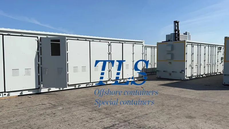
In offshore oil & gas exploration, marine research, and offshore wind projects, the traditional workflow of “offshore sampling – onshore laboratory testing” often leads to long testing cycles, high logistics costs, and sample contamination risks. TLS’s 20ft Offshore Mobile Laboratory Container is designed for safe-area offshore operations, allowing laboratory analysis capabilities to be deployed directly onsite for real-time testing and faster operational decision-making.
This article answers several key questions:
Why Are More Offshore Projects Adopting Mobile Laboratory Containers?
Under traditional offshore workflows, drilling fluids, core samples, water samples, and environmental samples often need to be transported back to onshore laboratories for analysis, resulting in delays of days or even weeks.
TLS Offshore Mobile Laboratory Containers enable onsite testing for:
Compared with building permanent offshore laboratories, TLS modular laboratory solutions require no complex structural modifications and offer:
Designed for Harsh Offshore EnvironmentsMarine-Grade Anti-Corrosion and High-Strength Structure
TLS Offshore Laboratory Containers are manufactured with weather-resistant steel and industrial-grade anti-corrosion systems to withstand:
Precision HVAC Climate Control
Laboratory instruments require stable environmental conditions for accurate operation.
TLS integrates industrial-grade HVAC systems capable of:
Plug-and-Play Deployment
TLS Offshore Laboratory Containers can integrate:
Why Choose TLS?
TLS specializes in modular offshore functional containers and customized special container solutions, offering:
Conclusion: Three Key Considerations When Selecting an Offshore Mobile Laboratory
When evaluating offshore laboratory containers, operators should focus on the following key factors:
1. Standardized Logistics and Fast Deployment Capability
Standard 20ft ISO dimensions improve transportation compatibility and offshore relocation efficiency.
2. Reliable Temperature and Humidity Control
In high-salinity and high-humidity environments, HVAC precision and anti-condensation performance directly affect testing accuracy and equipment lifespan.
3. Long-Term Marine Corrosion Protection
High-quality anti-corrosion systems and highly prefabricated designs help reduce maintenance requirements and extend operational lifecycle.
TLS 20ft Offshore Mobile Laboratory Containers are more than transportable laboratory spaces — they are high-performance onsite scientific analysis platforms for modern offshore operations. As offshore industries continue moving toward greater efficiency and digitalization, mobile laboratory containers are becoming an increasingly important part of future offshore infrastructure.
TLS Offshore Containers / TLS Energy is a global supplier of standard and customised containerised solutions.
Wherever you are in the world, TLS can help you. Please contact us.
Product brochures:
Offshore total pressurised container solutions
Offshore pressurised mud logging cabin brochure
MCC | Switchgear | VFD | VSD pressurised shelter
Keywords:#Offshore Mobile Laboratory Container,#Offshore Laboratory Container,#Offshore Lab Container Solution,#20ft Offshore Laboratory Container,#Marine Laboratory Container#Offshore Testing Laboratory,#Modular Offshore Laboratory,#Offshore Oil and Gas Laboratory Container,#Offshore Wind Laboratory Container,#Mobile Laboratory Container for Offshore Projects
In offshore oil & gas exploration, marine research, and offshore wind projects, the traditional workflow of “offshore sampling – onshore laboratory testing” often leads to long testing cycles, high logistics costs, and sample contamination risks. TLS’s 20ft Offshore Mobile Laboratory Container is designed for safe-area offshore operations, allowing laboratory analysis capabilities to be deployed directly onsite for real-time testing and faster operational decision-making.
This article answers several key questions:
- Why are offshore mobile laboratories becoming increasingly important for offshore operations?
- How can laboratory equipment remain stable in high-salinity, high-humidity, and dynamic marine environments?
- How do offshore laboratory containers achieve plug-and-play deployment?
- Which offshore industries and applications are best suited for mobile laboratory solutions?
Why Are More Offshore Projects Adopting Mobile Laboratory Containers?
Under traditional offshore workflows, drilling fluids, core samples, water samples, and environmental samples often need to be transported back to onshore laboratories for analysis, resulting in delays of days or even weeks.
TLS Offshore Mobile Laboratory Containers enable onsite testing for:
- Drilling fluid analysis
- Core sample testing
- Water quality monitoring
- Chemical analysis
- Environmental parameter testing
Compared with building permanent offshore laboratories, TLS modular laboratory solutions require no complex structural modifications and offer:
- Standard 20ft ISO dimensions
- Global transportation compatibility
- Fast lifting and relocation capability
- Multi-project reusability
Designed for Harsh Offshore EnvironmentsMarine-Grade Anti-Corrosion and High-Strength Structure
TLS Offshore Laboratory Containers are manufactured with weather-resistant steel and industrial-grade anti-corrosion systems to withstand:
- High salt spray exposure
- High humidity conditions
- Vessel vibration and movement
- Dynamic offshore impacts
Precision HVAC Climate Control
Laboratory instruments require stable environmental conditions for accurate operation.
TLS integrates industrial-grade HVAC systems capable of:
- Precise temperature and humidity control
- Condensation prevention
- Continuous air circulation
- Stable internal microclimate management
Plug-and-Play Deployment
TLS Offshore Laboratory Containers can integrate:
- Fire detection systems
- Gas suppression systems
- Emergency lighting
- Electrical quick-connect interfaces
- Water supply, drainage, and communication interfaces
Why Choose TLS?
TLS specializes in modular offshore functional containers and customized special container solutions, offering:
- ISO-standard modular design
- Marine-grade anti-corrosion structure
- Customized laboratory layouts
- Integrated HVAC and utility systems
- Offshore safety-compliant design
- Rapid deployment capability
Conclusion: Three Key Considerations When Selecting an Offshore Mobile Laboratory
When evaluating offshore laboratory containers, operators should focus on the following key factors:
1. Standardized Logistics and Fast Deployment Capability
Standard 20ft ISO dimensions improve transportation compatibility and offshore relocation efficiency.
2. Reliable Temperature and Humidity Control
In high-salinity and high-humidity environments, HVAC precision and anti-condensation performance directly affect testing accuracy and equipment lifespan.
3. Long-Term Marine Corrosion Protection
High-quality anti-corrosion systems and highly prefabricated designs help reduce maintenance requirements and extend operational lifecycle.
TLS 20ft Offshore Mobile Laboratory Containers are more than transportable laboratory spaces — they are high-performance onsite scientific analysis platforms for modern offshore operations. As offshore industries continue moving toward greater efficiency and digitalization, mobile laboratory containers are becoming an increasingly important part of future offshore infrastructure.
TLS Offshore Containers / TLS Energy is a global supplier of standard and customised containerised solutions.
Wherever you are in the world, TLS can help you. Please contact us.
Product brochures:
Offshore total pressurised container solutions
Offshore pressurised mud logging cabin brochure
MCC | Switchgear | VFD | VSD pressurised shelter
Keywords:#Offshore Mobile Laboratory Container,#Offshore Laboratory Container,#Offshore Lab Container Solution,#20ft Offshore Laboratory Container,#Marine Laboratory Container#Offshore Testing Laboratory,#Modular Offshore Laboratory,#Offshore Oil and Gas Laboratory Container,#Offshore Wind Laboratory Container,#Mobile Laboratory Container for Offshore Projects
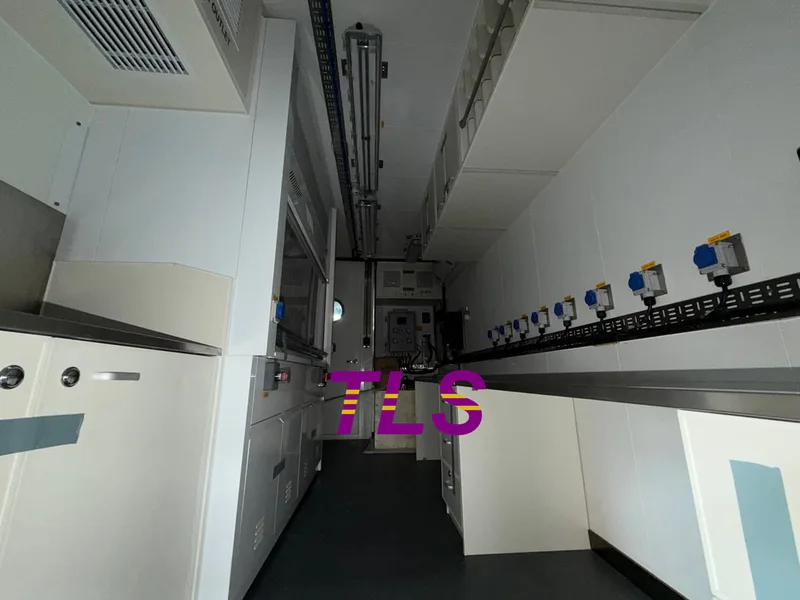
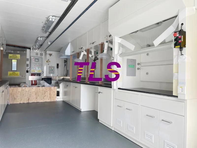
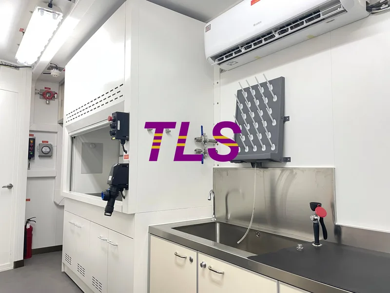
Written by Snowy
- Published on
Overview: In desert oilfields, offshore platforms, polar stations, and remote mining sites, accommodation containers are no longer just temporary shelters. They have become critical living spaces where personnel rest, recover, and maintain operational readiness during long-term deployments.
For projects involving extended on-site stays, a reliable accommodation module must address much more than basic shelter. The real challenges are often practical and continuous:
1. Thermal Insulation & Climate Control: More Than Just Installing an Air Conditioner
In high-temperature deserts or extremely cold regions, standard containers often suffer from:
Multi-Layer Insulation Structure
TLS accommodation containers typically adopt a multi-layer insulated wall structure that includes:
At the same time, the container design aims to reduce thermal bridging effects, preventing steel structural members from directly transferring heat or cold into the interior.
The goal is not simply fast cooling or heating — it is maintaining a stable indoor temperature over long operating periods.
Climate Control Designed for Industrial Projects
Unlike standard residential systems, long-term industrial accommodation projects require:
2. Structural Safety: Accommodation Modules Also Protect Personnel
In offshore, mining, and remote industrial projects, accommodation containers often experience:
High-Strength Steel Structural Design
TLS accommodation modules utilize fully welded steel frame structures designed to enhance:
Protection for Harsh Environments
Depending on project conditions, TLS focuses on:
3. Long-Term Living Comfort: More Than Just a Place to Sleep
For personnel stationed on-site for extended periods, accommodation quality directly impacts:
Air Quality & Ventilation Design
While highly sealed structures help isolate harsh external environments, they may also reduce indoor air quality.
TLS accommodation containers are designed with provisions for:
Space Layout & Noise Reduction
Within limited container dimensions, the interior layout must balance:
4. Modular Design: Flexible for Different Project Scales
Project requirements can vary significantly depending on workforce size and operational functions.
TLS modular accommodation containers can support:
Conclusion
In extreme environment projects, accommodation containers are far more than temporary shelters.
They directly influence:
For long-term field operations, the true value of an accommodation container is not defined by how many features it includes — but by whether it can continuously provide a stable, safe, and comfortable living environment under demanding conditions.
More information about accommodation modules, offshore accommodation cabins, gallery module, mess module, etc. Please download the TLS accommodation modular brochure, TLS 20ft offshore accommodation container, and TLS ABS-approved offshore accommodation module brochure for reference.
Keywords: #Modular accommodation container,#Extreme environment accommodation,#Offshore accommodation module,#Remote camp container solutions,#Modular living container,#Mining camp accommodation,#Insulated accommodation container,#Containerized living quarters,#Modular workforce housing,#Long-term accommodation container
For projects involving extended on-site stays, a reliable accommodation module must address much more than basic shelter. The real challenges are often practical and continuous:
- Can the interior remain comfortable despite extreme outdoor temperature fluctuations?
- Will the structure withstand strong winds, salt spray, sandstorms, and repeated transportation?
- Can air quality, humidity, and noise levels support long-term human wellbeing?
- How can limited space still provide practical living, storage, and resting functions?
- Environmental adaptability
- Structural safety
- Long-term living comfort
1. Thermal Insulation & Climate Control: More Than Just Installing an Air Conditioner
In high-temperature deserts or extremely cold regions, standard containers often suffer from:
- Excessive indoor heat during summer
- Severe heat loss during winter
- Condensation on internal walls
- Uneven temperature distribution
Multi-Layer Insulation Structure
TLS accommodation containers typically adopt a multi-layer insulated wall structure that includes:
- High-density rock wool insulation
- High-strength steel exterior panels
At the same time, the container design aims to reduce thermal bridging effects, preventing steel structural members from directly transferring heat or cold into the interior.
The goal is not simply fast cooling or heating — it is maintaining a stable indoor temperature over long operating periods.
Climate Control Designed for Industrial Projects
Unlike standard residential systems, long-term industrial accommodation projects require:
- Continuous operation capability
- Adaptation to extreme climates
- Stable temperature control
- Low failure rates
2. Structural Safety: Accommodation Modules Also Protect Personnel
In offshore, mining, and remote industrial projects, accommodation containers often experience:
- Repeated lifting operations
- Combined sea and land transportation
- High wind pressure environments
- High humidity and salt spray corrosion
High-Strength Steel Structural Design
TLS accommodation modules utilize fully welded steel frame structures designed to enhance:
- Lifting strength
- Structural torsion resistance
- Long-distance transportation stability
- Reduced risk of deformation and fatigue damage during long-term use
Protection for Harsh Environments
Depending on project conditions, TLS focuses on:
- Anti-corrosion coating systems
- Moisture protection
- Wind resistance
- Seismic stability
3. Long-Term Living Comfort: More Than Just a Place to Sleep
For personnel stationed on-site for extended periods, accommodation quality directly impacts:
- Rest and sleep quality
- Daily work performance
- Fatigue recovery
- Psychological comfort
Air Quality & Ventilation Design
While highly sealed structures help isolate harsh external environments, they may also reduce indoor air quality.
TLS accommodation containers are designed with provisions for:
- Fresh air system interfaces
- Exhaust systems
- Optimized ventilation pathways
Space Layout & Noise Reduction
Within limited container dimensions, the interior layout must balance:
- Sleeping areas
- Storage space
- Sanitary facilities
- Walking and access space
- Wall sound insulation
- Sealed doors and windows
- Equipment vibration reduction
4. Modular Design: Flexible for Different Project Scales
Project requirements can vary significantly depending on workforce size and operational functions.
TLS modular accommodation containers can support:
- Horizontal expansion
- Multi-level stacking
- Functional area combinations
- Dormitories
- Dining areas
- Offices
- Public recreation spaces
Conclusion
In extreme environment projects, accommodation containers are far more than temporary shelters.
They directly influence:
- Personnel safety
- Long-term operational stability
- Living comfort
- Overall project efficiency
For long-term field operations, the true value of an accommodation container is not defined by how many features it includes — but by whether it can continuously provide a stable, safe, and comfortable living environment under demanding conditions.
More information about accommodation modules, offshore accommodation cabins, gallery module, mess module, etc. Please download the TLS accommodation modular brochure, TLS 20ft offshore accommodation container, and TLS ABS-approved offshore accommodation module brochure for reference.
Keywords: #Modular accommodation container,#Extreme environment accommodation,#Offshore accommodation module,#Remote camp container solutions,#Modular living container,#Mining camp accommodation,#Insulated accommodation container,#Containerized living quarters,#Modular workforce housing,#Long-term accommodation container