- Published on
Battery Energy Storage Systems (BESS) play a vital role in modern power grids, renewable integration, and energy management. To design and operate a successful BESS project, it is essential to understand the basic concepts of power and energy, as these two parameters determine the system’s performance, application suitability, and return on investment.
What Is Power in BESS?
Power, measured in kilowatts (kW) or megawatts (MW), refers to the rate at which energy is delivered or consumed at a specific moment. In a BESS, power determines how quickly the system can charge or discharge. For example, a 10MW BESS can deliver up to 10 megawatts of power to the grid or a facility.
High power output is critical for applications that require fast response, such as:
• Frequency regulation
• Grid stabilization
• Short-duration peak shaving
• Black start support
In these use cases, the ability to inject or absorb large amounts of power in a short time is more important than how long the system can maintain it.
What Is Energy in BESS?
Energy, measured in kilowatt-hours (kWh) or megawatt-hours (MWh), represents the total amount of electricity a battery can store and deliver over time. It defines how long the system can operate at a given power level.
For example, a 20MWh BESS can supply 10MW of power for 2 hours, or 5MW for 4 hours, depending on the application.
High energy capacity is essential for applications like:
• Renewable energy integration
• Load shifting
• Backup power supply
• Off-grid operations
These use cases require the battery to deliver sustained energy over a longer duration, rather than high bursts of power.
Power vs. Energy: Why It Matters
When selecting or designing a BESS, understanding the difference between power and energy is critical. Systems can be:
• Power-oriented, with high MW rating and short discharge time (e.g., 1C or higher C-rate)
• Energy-oriented, with large MWh capacity and longer durations (e.g., 2–4 hours or more)
• Balanced, suitable for hybrid applications
Choosing the right ratio of power to energy depends on the project’s goals. For example, a 50MW/50MWh system is considered a 1-hour system and is common for grid services that need both power and limited energy.
TLS Energy’s Approach to BESS Design
At TLS Energy, we offer customized BESS solutions designed to match your specific power and energy needs. Our battery systems are engineered for safety, efficiency, and scalability. Whether you need short-duration frequency regulation or long-duration energy storage for renewable projects, TLS Energy provides the right balance of power and energy to optimize your investment.
Interested in a tailored BESS solution?
Contact TLS Energy today to discuss your project needs or explore our latest energy storage systems on our website.

- Published on
As the global energy landscape shifts toward renewable power and energy storage, Battery Energy Storage Systems (BESS) play a key role in stabilizing the grid, storing surplus energy, and improving power quality. One of the most critical components in any BESS is the Power Conversion System (PCS) — the heart of energy transformation between AC (grid) and DC (battery).
At TLS Energy, we understand that high conversion efficiency is not just a technical benchmark — it directly impacts the client’s operational cost, system reliability, and return on investment. That’s why we use advanced Silicon Carbide (SiC) IGBT technology in our PCS to ensure industry-leading efficiency and performance.
Real Performance: 99% Efficiency in Live Operation
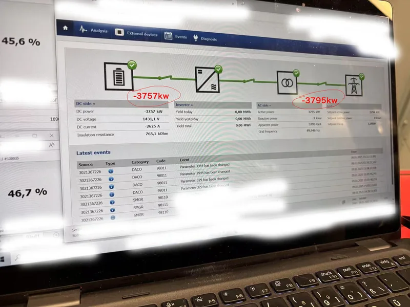
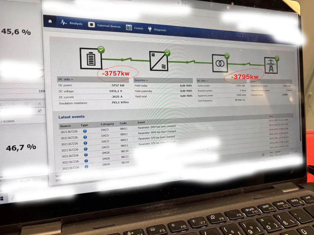
In one of TLS Energy’s active projects, a screenshot of the PCS interface shows the following real-time values:
• DC Power: 3757 kW
• AC Power: 3795 kW
This indicates that only 38 kW is lost during the power conversion process — a conversion efficiency of approximately 99%. This level of performance is exceptional and far exceeds traditional power electronics.
This impressive result is made possible by the use of SiC-based IGBT modules in our PCS.
What is SiC IGBT Technology?
SiC IGBT stands for Silicon Carbide Insulated-Gate Bipolar Transistor. It is a type of power semiconductor device used to switch and convert electricity at high efficiency and high voltage. SiC IGBT is considered the next generation of power devices, offering significant performance improvements over traditional silicon-based IGBT.
Key advantages of SiC IGBT include:
• High Switching Frequency
SiC devices can switch at much higher frequencies with lower losses, enabling more precise and responsive control of power.
• Low Switching and Conduction Losses
SiC IGBTs reduce energy losses during switching operations, helping achieve high overall system efficiency.
• High Thermal Conductivity
SiC handles higher operating temperatures, which reduces the size of the cooling system and improves system reliability.
• Smaller and Lighter PCS Design
With less heat and more efficient performance, the PCS design becomes more compact, reducing container space and installation cost.
Why SiC IGBT Is More Efficient Than Traditional Si IGBT
To understand why SiC IGBT enables such high energy efficiency, it’s important to compare it with traditional silicon (Si) IGBT technology. Here’s a breakdown:
How High Efficiency Saves Cost for Clients
For every megawatt-hour (MWh) stored and discharged by a BESS system, energy losses during conversion directly affect operational cost. A low-efficiency PCS can lead to significant energy losses, which adds up over the system’s lifetime.
With TLS Energy’s high-efficiency PCS:
• More energy is delivered to the grid or load
• Lower operational and cooling costs
• Improved system performance and lifespan
• Reduced carbon footprint
• Higher ROI for clients
For example, in a 100MWh BESS project, even a 1% efficiency improvement can save ~ half million of dollars annually in energy costs alone.
Applications That Benefit from High-Efficiency PCS
SiC IGBT-based PCS systems from TLS Energy are suitable for a wide range of applications:
• Utility-Scale Renewable Integration
Efficient conversion maximizes the value of stored solar or wind energy.
• Commercial & Industrial (C&I) Facilities
Businesses can reduce electricity bills and demand charges with reliable, high-efficiency energy storage.
• Microgrids and Off-Grid Systems
In isolated or remote areas, every watt counts. High-efficiency PCS ensures maximum battery usage.
• Frequency Regulation and Grid Services
Fast response and accurate control are supported by high switching speed of SiC IGBTs.
TLS Energy: Innovation Meets Reliability
At TLS Energy, we go beyond traditional EPC or container manufacturing — we are a full-solution BESS provider. From system design to delivery, we integrate the latest technology to help our clients achieve long-term value.
Key strengths of TLS Energy’s BESS solutions:
• Advanced PCS with SiC IGBT modules
• Modular and scalable design
• Integrated EMS, BMS, and SCADA
• Robust thermal and fire safety design
• Global compliance (CE, UL, IEC, DNV 2.7-1, etc.)
Our systems are tested under real-world conditions to deliver the performance, reliability, and efficiency demanded by the modern grid.
SiC IGBT technology is a game changer in energy storage power conversion. It allows PCS to operate with higher efficiency, better thermal performance, and compact design. TLS Energy’s adoption of this technology has proven results — our live project shows over 99% AC-DC efficiency, minimizing losses and maximizing value.
Whether your goal is to reduce energy costs, improve energy reliability, or support renewable energy adoption, TLS Energy offers a solution built for performance, safety, and long-term success.
Contact us today to learn more about how TLS Energy’s high-efficiency BESS systems can support your energy goals.
At TLS Energy, we understand that high conversion efficiency is not just a technical benchmark — it directly impacts the client’s operational cost, system reliability, and return on investment. That’s why we use advanced Silicon Carbide (SiC) IGBT technology in our PCS to ensure industry-leading efficiency and performance.
Real Performance: 99% Efficiency in Live Operation
In one of TLS Energy’s active projects, a screenshot of the PCS interface shows the following real-time values:
• DC Power: 3757 kW
• AC Power: 3795 kW
This indicates that only 38 kW is lost during the power conversion process — a conversion efficiency of approximately 99%. This level of performance is exceptional and far exceeds traditional power electronics.
This impressive result is made possible by the use of SiC-based IGBT modules in our PCS.
What is SiC IGBT Technology?
SiC IGBT stands for Silicon Carbide Insulated-Gate Bipolar Transistor. It is a type of power semiconductor device used to switch and convert electricity at high efficiency and high voltage. SiC IGBT is considered the next generation of power devices, offering significant performance improvements over traditional silicon-based IGBT.
Key advantages of SiC IGBT include:
• High Switching Frequency
SiC devices can switch at much higher frequencies with lower losses, enabling more precise and responsive control of power.
• Low Switching and Conduction Losses
SiC IGBTs reduce energy losses during switching operations, helping achieve high overall system efficiency.
• High Thermal Conductivity
SiC handles higher operating temperatures, which reduces the size of the cooling system and improves system reliability.
• Smaller and Lighter PCS Design
With less heat and more efficient performance, the PCS design becomes more compact, reducing container space and installation cost.
Why SiC IGBT Is More Efficient Than Traditional Si IGBT
To understand why SiC IGBT enables such high energy efficiency, it’s important to compare it with traditional silicon (Si) IGBT technology. Here’s a breakdown:
- Lower Switching Losses
- Lower Conduction Losses
- Higher Switching Frequency
- Higher Operating Temperatures
- Higher Voltage Blocking Capability
How High Efficiency Saves Cost for Clients
For every megawatt-hour (MWh) stored and discharged by a BESS system, energy losses during conversion directly affect operational cost. A low-efficiency PCS can lead to significant energy losses, which adds up over the system’s lifetime.
With TLS Energy’s high-efficiency PCS:
• More energy is delivered to the grid or load
• Lower operational and cooling costs
• Improved system performance and lifespan
• Reduced carbon footprint
• Higher ROI for clients
For example, in a 100MWh BESS project, even a 1% efficiency improvement can save ~ half million of dollars annually in energy costs alone.
Applications That Benefit from High-Efficiency PCS
SiC IGBT-based PCS systems from TLS Energy are suitable for a wide range of applications:
• Utility-Scale Renewable Integration
Efficient conversion maximizes the value of stored solar or wind energy.
• Commercial & Industrial (C&I) Facilities
Businesses can reduce electricity bills and demand charges with reliable, high-efficiency energy storage.
• Microgrids and Off-Grid Systems
In isolated or remote areas, every watt counts. High-efficiency PCS ensures maximum battery usage.
• Frequency Regulation and Grid Services
Fast response and accurate control are supported by high switching speed of SiC IGBTs.
TLS Energy: Innovation Meets Reliability
At TLS Energy, we go beyond traditional EPC or container manufacturing — we are a full-solution BESS provider. From system design to delivery, we integrate the latest technology to help our clients achieve long-term value.
Key strengths of TLS Energy’s BESS solutions:
• Advanced PCS with SiC IGBT modules
• Modular and scalable design
• Integrated EMS, BMS, and SCADA
• Robust thermal and fire safety design
• Global compliance (CE, UL, IEC, DNV 2.7-1, etc.)
Our systems are tested under real-world conditions to deliver the performance, reliability, and efficiency demanded by the modern grid.
SiC IGBT technology is a game changer in energy storage power conversion. It allows PCS to operate with higher efficiency, better thermal performance, and compact design. TLS Energy’s adoption of this technology has proven results — our live project shows over 99% AC-DC efficiency, minimizing losses and maximizing value.
Whether your goal is to reduce energy costs, improve energy reliability, or support renewable energy adoption, TLS Energy offers a solution built for performance, safety, and long-term success.
Contact us today to learn more about how TLS Energy’s high-efficiency BESS systems can support your energy goals.
- Published on
When evaluating a Battery Energy Storage System (BESS), many project owners tend to focus primarily on the initial price. However, this short-term thinking can lead to long-term losses. To truly maximize return on investment and system performance, it’s important to look beyond initial investment and consider deeper technical factors—especially battery durability, power conversion efficiency, and system reliability.
1. Battery Durability: Designed for Long-Term Use
Battery cell quality directly affects both performance and lifecycle cost. Some low-cost batteries may begin degrading after just 2,000 cycles—leading to reduced capacity, rising internal resistance, and frequent performance issues.
In contrast, high-quality lithium iron phosphate (LFP) batteries with proper thermal and BMS design can deliver more than 8,000 charging and discharging cycles under standard operating conditions. This long cycle life ensures stable performance, fewer replacements, and a much lower total cost of ownership throughout the system’s 10–15 year lifespan.
2. Efficiency on the power conversion: Every 1% Means Big Money
Many buyers overlook power conversion round-trip efficiency, which measures the actual usable energy delivered to the grid after accounting for losses from the power conversion system (PCS) and transformer.
Most standard PCS units in the market achieve about 95% power conversion efficiency. At TLS Energy, our systems are optimized to reach up to 99%. Though a 4% difference may seem small, it has a massive impact when scaled across daily operations.
Every 1% increase in conversion efficiency can save approximately half millions annually for a 100MWh BESS project running daily. This kind of efficiency not only lowers energy waste, but also boosts overall project profitability.
3. Reliability Reduces Downtime and O&M Costs
In energy storage systems, unplanned shutdowns and maintenance downtime can be extremely costly—both in lost revenue and repair work. Using high-quality battery systems and reliable PCS components significantly reduces the chance of system failure.
Fewer shutdowns mean:
• More uptime and energy output
• Less frequent service interruptions
• Lower maintenance cost
• Higher overall project availability
This is especially critical for grid-connected systems and commercial applications where reliability is non-negotiable.
4. Total Lifecycle Cost Is What Really Matters
Choosing a BESS should never be about the lowest bid. True value comes from:
• Long battery lifespan
• High conversion efficiency
• Low maintenance and downtime
• Strong long-term performance
Many buyers focus only on CAPEX--Capital Expenditure, which is the upfront cost of purchasing and installing the system. However, a more important metric is the total lifecycle cost, which includes energy efficiency, maintenance, downtime, and replacement over 10–15 years.
TLS Energy focuses on delivering high-efficiency, low-risk energy storage systems that are optimized for total lifecycle value. Every component—from the battery modules to PCS and transformer—is selected to reduce energy loss, lower operating expenses, and extend asset life.
When planning a BESS project, don’t just ask “What’s the price today?”—ask “How much will this system save me every year for the next 10–15 years?”
TLS Energy helps project owners and EPCs make smarter energy investments by delivering durable, efficient, and reliable BESS solutions built for long-term success.
Contact TLS Energy today to find out how we can support your next energy storage project.

- Published on
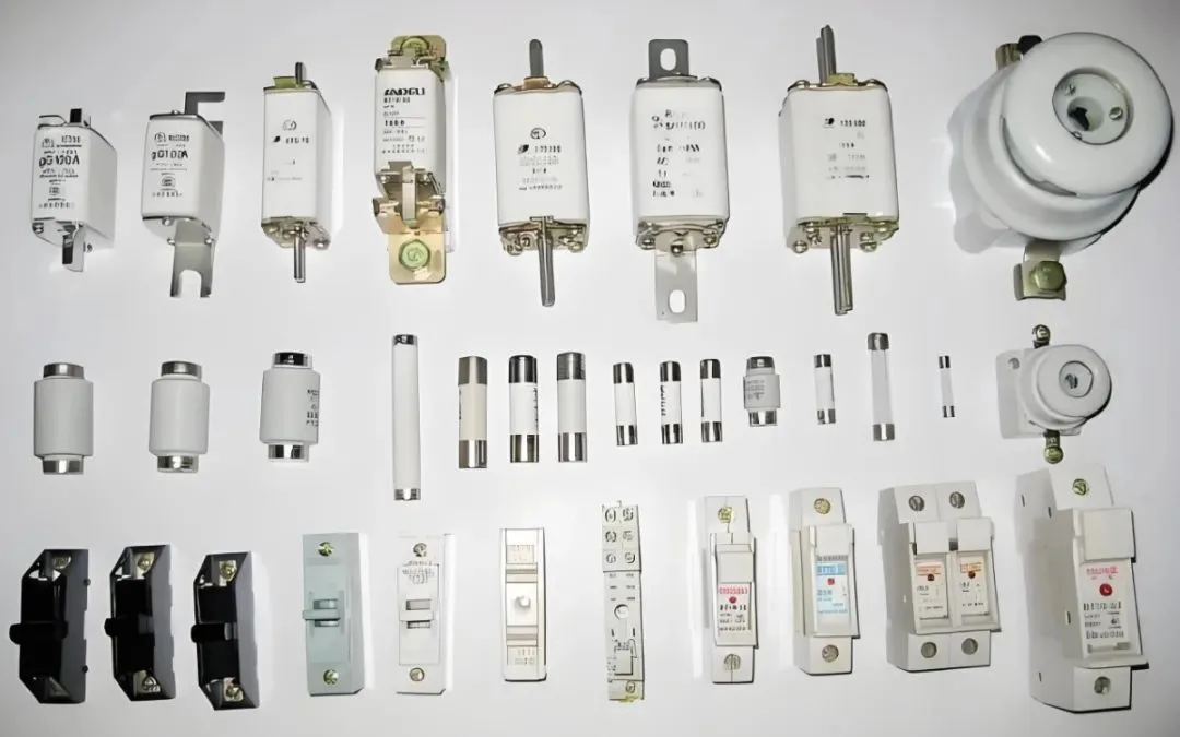
DC fuses play a crucial role in protecting Battery Energy Storage Systems (BESS) from short-circuit and overcurrent faults. Unlike traditional AC systems, BESS presents unique challenges due to high DC voltages, rapid current rise times, and energy-intensive fault conditions. Therefore, selecting the right fuse based on core parameters is essential for system safety, longevity, and performance.
DC Fuse Types and Classification
A DC fuse typically consists of a fusible element, quartz sand, and metal end caps. According to the GB13539.1-2015 standard, fuses are classified using a two-letter code. The first letter denotes the breaking range:
• “g” indicates full-range protection for overload and short-circuit conditions.
• “a” indicates partial-range protection (backup protection), which must be used with other devices.
The second letter indicates the application:
• “G” for general conductors,
• “M” for motor circuits,
• “R” for semiconductors.
For instance, a gG fuse provides full-range protection for general applications, while an aR fuse is ideal for fast protection of sensitive semiconductor components.
Key Parameters: Ft Value and Breaking Capacity
Three critical parameters define a DC fuse’s performance:
1. Rated current – the maximum continuous current the fuse can carry.
2. Breaking capacity – the highest fault current the fuse can safely interrupt.
3. Pre-arcing I²t (Ft value) – the energy the fuse can absorb before opening the circuit.
The Ft value is vital for ensuring selective coordination. In multi-stage protection systems, the downstream fuse must have a lower Ft value than the upstream fuse’s minimum pre-arcing Ft. This ensures only the nearest fuse to the fault operates, avoiding unnecessary power outages in other parts of the system.
For faults lasting less than 0.1 seconds, coordination must be verified by comparing Ft values. For faults over 0.1 seconds, the time-current characteristic curve is used to confirm selectivity.
Arc Quenching Process and Material Considerations
A fuse operates in four stages: heating, melting, arcing, and arc extinguishing. Once a fault occurs, the fusible link heats rapidly and melts, creating an arc. Quartz sand, filled around the fuse element, acts as an arc suppressor. It absorbs energy and forms a high-resistance “lava” layer that quenches the arc within milliseconds.
Factors like sand grain size and filling density directly affect quenching efficiency. Additionally, the fuse element material—commonly silver or copper—must balance conductivity, melting point, and cost for reliable performance at different voltage levels.
Fuse Application in BESS Systems
In large-scale BESS installations, short-circuit currents can exceed tens of kiloamperes. This requires fuses with very high breaking capacity, such as gR-type fuses.
Multiple fuse levels are often used in series—main circuit fuses with higher current ratings, and branch circuit fuses with faster response times. To maintain proper selectivity, Ft values between stages must differ by a factor of at least 1.5. In some designs, limiting reactors are added to reduce mutual inductance effects in parallel branches and assist in fault current limitation.
- Published on
As the demand for battery energy storage systems (BESS) continues to grow, especially for commercial, industrial, and utility-scale applications, the use of 20ft ISO containers has become a popular and widely accepted standard. Their size, structure, and flexibility make them an ideal solution for containerized energy storage systems. Below are the key reasons why 20ft containers are so commonly used in this field.
1. Standardized Size for Global Compatibility
The 20ft ISO container, with dimensions of 6058mm (length) × 2438mm (width) × 2591mm (height), is a globally recognized shipping standard. This means it is fully compatible with international logistics, including sea freight, land transport, and railways.
Using standardized containers reduces logistical complexity and costs. It also ensures that storage systems can be deployed globally without needing custom packaging or transport solutions, making project planning and execution more efficient.
2. Modular Design for Fast Deployment and Scalability
The 20ft container offers a compact and efficient space for housing key components of the battery system, including battery racks, battery management systems (BMS), HVAC, fire suppression systems, and communication units. By using a modular design, each container functions as a standalone storage unit.
This modularity allows for:
• Easy expansion of storage capacity by simply adding more containers.
• Faster onsite deployment, as most of the assembly and integration is done at the factory.
• Simplified maintenance, as each container can be serviced independently.
3. Lightweight for Easier Land and Sea Transport
Compared to 40ft containers, 20ft containers are significantly lighter, which offers great advantages in both land and sea transport. In areas with restricted access or limited infrastructure—such as islands, mountain regions, or remote industrial sites—the lighter weight and smaller footprint make 20ft containers easier to maneuver, offload, and install.
This is especially beneficial for projects that require flexibility in logistics and fast turnaround times.
4. Optimized for Safety and Thermal Management
Each 20ft container typically houses 2 to 6MWh of battery capacity, a manageable volume that allows for safer operation and easier thermal control. This moderate energy density enables:
• Efficient integration of air or liquid cooling systems.
• Better zoning and separation for fire safety.
• Easier compliance with international standards like NFPA 855, UL9540A, or IEC 62933.
In the case of any malfunction or fire event, having energy distributed across multiple 20ft containers helps isolate risks and prevent chain reactions.
5. Cost-Effective and Reusable
ISO containers are built to be robust and durable. They can be reused for multiple deployments, making them more sustainable and cost-effective in the long run. Since they already conform to international container standards, less customization is required for transport and installation, further reducing overall project costs.
The 20ft ISO container has become the preferred choice for containerized energy storage solutions due to its standardization, modularity, lighter weight, safety benefits, and cost efficiency. As the BESS market continues to expand, using 20ft containers ensures flexible, scalable, and globally deployable solutions that meet both operational and regulatory demands.
- Published on
Frequency regulation is a critical part of maintaining stability in power systems. It ensures that the balance between power generation and consumption keeps the system frequency within acceptable limits. Two key components of frequency control are primary frequency regulation and secondary frequency regulation. Each serves a unique purpose and works at different timescales, but both are vital to grid stability—especially with the increasing penetration of renewable energy. Battery Energy Storage Systems (BESS) are emerging as an essential solution in this context.
What is Primary Frequency Regulation?
Primary frequency regulation is an automatic response from generator units when grid frequency deviates from the nominal value (e.g., 50 Hz). It works through the turbine governor system, which rapidly adjusts output power—usually within seconds. However, this adjustment is proportional and incomplete, meaning it reduces but does not eliminate the frequency deviation. The fast-acting nature of primary regulation is designed to stabilize short-term disturbances caused by sudden load or generation changes.
What is Secondary Frequency Regulation?
Secondary frequency regulation, also known as Automatic Generation Control (AGC), is a slower, more precise correction. It aims to restore frequency to its nominal value and ensure that inter-area power exchanges remain within scheduled limits. AGC operates over a timescale of several minutes and involves centralized dispatch signals sent by grid operators to specific generators or energy storage systems. This type of regulation is essential for long-term frequency stability and often responds to the residual imbalance after primary regulation.
Advantages of Battery Energy Storage Systems in Frequency Regulation
Battery Energy Storage Systems provide a new, highly flexible resource for frequency regulation, offering several advantages over traditional generation:
• Fast Response: BESS can switch between charge and discharge in milliseconds—far faster than thermal generators. This enables immediate correction of frequency fluctuations, especially during primary frequency control.
• Precision: Energy storage systems offer high accuracy in power output control, which is critical for secondary regulation. This precision enhances the overall reliability and performance of the grid.
• Eco-Friendly: Unlike fossil-fuel generators, BESS produce no emissions, making them ideal for integrating with clean energy sources such as wind and solar.
• Cost-Effective: With rising penalties and performance assessments for AGC services, BESS can help traditional plants meet strict regulation requirements and earn additional revenue through grid ancillary service markets.
Primary and secondary frequency regulation work together to ensure the stable and secure operation of power systems. As grid complexity increases, especially with more renewable energy sources, battery energy storage stands out as a reliable, fast, and green solution for frequency control. By participating in both types of frequency regulation, BESS not only supports grid stability but also drives the transition toward a smarter, cleaner energy future.
- Published on
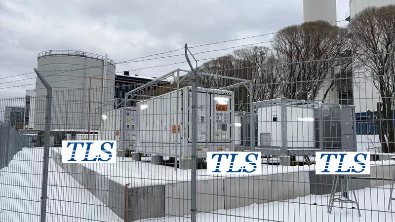
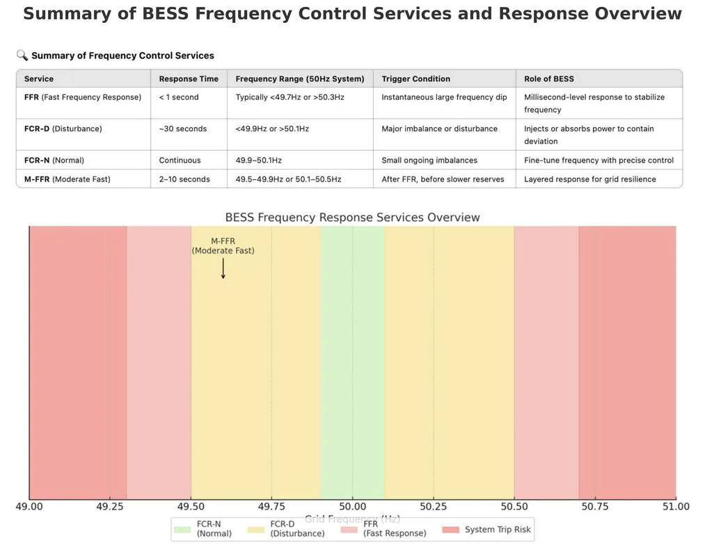
As global power grids shift toward renewable energy, maintaining frequency stability becomes increasingly complex. Traditional generation sources, such as coal and gas plants, provide natural system inertia, which helps dampen frequency deviations. However, with more solar and wind power integrated into the grid, the system’s ability to stabilize frequency declines. To address this challenge, Battery Energy Storage Systems (BESS) are now playing a critical role in delivering fast, precise frequency response services. Key among these are FFR (Fast Frequency Response), FCR-D (Frequency Containment Reserve – Disturbance), FCR-N (Frequency Containment Reserve – Normal), and M-FFR (Moderate Fast Frequency Response).
1. FFR (Fast Frequency Response)
FFR is the fastest frequency control service, typically activated within 1 second or less when system frequency experiences a sharp dip or rise. This service is crucial in the early moments of a disturbance—before traditional generators can ramp up. For example, if frequency drops below a threshold (e.g., 49.7Hz in a 50Hz system), BESS automatically discharges energy to help stabilize the grid.
Thanks to their millisecond-level response times and inverter-based architecture, BESS are ideal for delivering FFR. This makes them especially valuable in power systems with low inertia and high renewable penetration, where traditional mechanical generators are too slow to react.
2. FCR-D (Frequency Containment Reserve – Disturbance)
FCR-D is designed to respond to larger frequency deviations outside the normal operating range—typically below 49.9Hz or above 50.1Hz. It kicks in within 30 seconds and works to contain the disturbance until slower reserves or rebalancing measures take over.
BESS are well-suited for FCR-D services due to their ability to provide both symmetrical and asymmetrical support—either injecting or absorbing power depending on whether the frequency drops or spikes. This service is widely used in Nordic and Baltic markets and requires a stable, controllable, and fast-acting source of power regulation, making BESS a natural fit.
3. FCR-N (Frequency Containment Reserve – Normal)
Unlike FFR and FCR-D, which are triggered by significant events, FCR-N provides continuous frequency balancing during normal grid operation (within 49.9–50.1Hz). It is used to smooth out small, ongoing imbalances between generation and load.
BESS systems excel at this task because they can make precise power adjustments in real time. Whether charging or discharging, BESS ensure the system frequency stays as close as possible to its nominal value. FCR-N is essential for grid operators to maintain high-quality, stable power in systems with variable demand and fluctuating renewable generation.
4. M-FFR (Moderate Fast Frequency Response)
M-FFR is a medium-speed frequency response, designed to fill the gap between ultra-fast FFR and slower reserves like FCR-D. It typically activates within 2 to 10 seconds after a frequency event. This staged approach to frequency control helps ensure stability throughout the entire response timeline.
BESS provide an excellent platform for M-FFR due to their flexible control systems, allowing them to layer response times and power levels as needed. This adds resilience to the grid by supporting both initial shock absorption and continued stabilization.
Why BESS is Ideal for Frequency Regulation
Battery energy storage offers multiple advantages in frequency regulation:
• Ultra-fast response times
• High precision control
• Emission-free operation
• Reduced wear and maintenance compared to traditional generators
As frequency control becomes more dynamic and layered, BESS are becoming essential assets for transmission operators and energy providers worldwide.
FFR, FCR-D, FCR-N, and M-FFR form the backbone of modern frequency regulation strategies. Each service plays a unique role in stabilizing power systems, from milliseconds to minutes after a disturbance. Battery Energy Storage Systems, with their speed, accuracy, and flexibility, are uniquely positioned to deliver all these services effectively. As the energy transition accelerates, integrating BESS for grid support will be critical to ensuring a reliable, sustainable future.
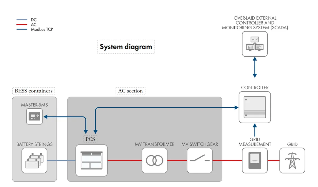
BESS system diagram for grid frequency control services.
- Published on
In photovoltaic (PV) power systems, the inverter plays a critical role in converting DC electricity from solar panels into AC power for grid use. At the heart of this conversion lies the IGBT (Insulated Gate Bipolar Transistor) module — a power device essential for high-efficiency switching. However, IGBT module failure, especially explosion due to stress or overheating, is a common and serious issue that can lead to equipment shutdowns or even fire hazards.
How IGBT Modules Work
IGBT modules are semiconductor devices that combine the benefits of MOSFETs and BJTs, offering fast switching speeds and low conduction loss. By controlling gate voltage, they switch on or off to regulate current flow and frequency. Their performance directly affects inverter efficiency and system reliability.
Common Causes of IGBT Failure
IGBT failure usually results from excessive internal heat or external electrical stress. Key reasons include:
1. Electrical Stress
•. Overvoltage: Transients like grid voltage spikes, lightning strikes, or reverse recovery voltage can exceed IGBT limits and cause dielectric breakdown.
•. Overcurrent: Sudden load changes, short circuits, or motor stalling may create current surges. If the protection circuit response is delayed (over 10µs), the module can overheat and rupture.
•. Drive Circuit Issues: Low gate voltage or signal noise can cause partial conduction, increasing power loss and local heat buildup.
2. Thermal Management Failures
•. Poor heat dissipation due to faulty fans, high ambient temperatures, or insufficient cooling can raise junction temperatures above safe limits (>150°C), causing material stress and eventual failure.
3. Design and Assembly Defects
•. Lack of buffer circuits, aged capacitors, or improper soldering and torque during installation can lead to increased contact resistance and heat.
4. External Factors and Human Error
•. Grid anomalies, unbalanced three-phase loads, or wiring mistakes can cause short circuits. Maintenance without proper ESD precautions can also damage sensitive components.
Emergency Handling After IGBT Failure
If an IGBT explosion occurs:
•. Shut down power immediately.
•. Inspect the system for smoke, fire, or visible damage.
•. Check driver voltages, DC bus capacitors, and absorption circuits.
•. Use a multimeter to verify if the IGBT is shorted.
•. Replace with a matching module, applying thermal paste and correct torque to ensure good contact.
Key Prevention Measures
•. Circuit Optimization: Use RC snubbers or TVS diodes to limit voltage spikes. Install fast fuses and current sensors for quick protection.
•. Proper Component Selection: Choose IGBTs with at least 2x voltage and sufficient current margin.
•. Enhanced Cooling: Use forced air or liquid cooling systems. Regularly clean heatsinks and verify fan operation.
•. Routine Monitoring: Use IR thermography and oscilloscopes to spot early faults. Design PCBs to minimize interference.
•. Staff Training: Educate operators on IGBT operation and failure modes. Install real-time monitoring to track temperature, voltage, and current.
IGBT failures in solar inverters are complex but preventable. By understanding the root causes and applying targeted design, monitoring, and maintenance strategies, system operators can reduce failure risk, extend equipment life, and ensure safer, more reliable PV operations.
- Published on
In modern construction and exploration projects, accommodation containers have evolved beyond being simple “sleeping spaces.” With growing demands and rapid technological advancements, accommodation containers have transformed into multifunctional facilities that integrate living, working, leisure, and medical spaces. In this blog, we will focus on how accommodation containers address industry challenges and leverage flexibility to play a key role in various projects.
1. Accommodation Containers: Beyond Traditional Lodging
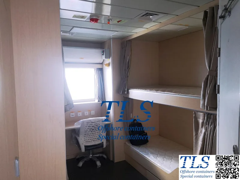
Traditionally, accommodation containers were viewed merely as temporary lodging solutions. However, modern accommodation containers have broken this mold, becoming flexible, customizable spaces for both work and living. Whether on construction sites, offshore platforms, mining operations, or emergency response areas, these containers not only provide comfortable living quarters but can also be equipped with offices, meeting rooms, dining areas, storage spaces, and even medical stations.
The core advantage of accommodation containers lies in their flexibility. They can be tailored to meet the specific needs of a project. For example, on a construction site, the container might need to include sleeping areas, storage, and office space. On an offshore platform, in addition to basic lodging, containers must be designed to withstand strong winds, moisture, and other extreme conditions. This flexibility in design maximizes both worker comfort and operational efficiency.
2. Solving Industry Pain Points: Adapting to Harsh Environments
Accommodation challenges become particularly significant in extreme environments. Construction sites, oil exploration, and offshore platforms face harsh weather conditions and demanding working environments, which require more robust accommodation solutions. Modern accommodation containers have been optimized to meet these needs, providing practical and reliable solutions.
For example, in desert or frigid regions, containers are equipped with insulation and climate control systems, ensuring a comfortable indoor temperature, even in the harshest climates. At the same time, these containers are built with features like windproof, moisture-resistant, and corrosion-resistant designs, allowing them to operate reliably in extreme conditions—whether it's a storm, heavy snowfall, or intense heat—while providing safe shelter for workers.
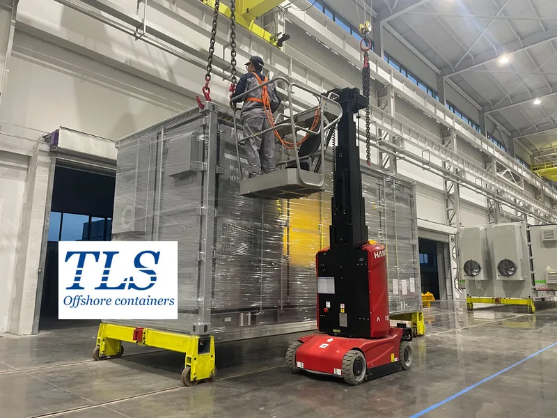
Another key advantage of accommodation containers is their modular design. Whether it's a construction site or an emergency response operation, containers can be quickly assembled or disassembled and relocated as needed. As project requirements shift—whether due to changes in the number of workers, project progress, or environmental conditions—containers offer the flexibility to adjust and continue operations efficiently.
3. Smart and Eco-friendly Design: The Future of Accommodation Containers
In addition to flexibility and environmental adaptability, smart technology and eco-friendly design are also key trends in modern accommodation containers. By incorporating Internet of Things (IoT) technologies, these containers can manage temperature control, lighting, and remote monitoring, optimizing both energy efficiency and comfort. Furthermore, energy-efficient designs and the use of eco-friendly materials reduce energy consumption and environmental impact, aligning with sustainable development goals.
Looking ahead, as globalization and customization demands increase, accommodation containers will become even more personalized and diverse. They will meet the evolving needs of various industries, establishing themselves as a reliable solution across sectors.
Conclusion
Accommodation containers have evolved from simple temporary housing to flexible, intelligent, and eco-friendly multifunctional spaces. With customizable designs, they address critical industry challenges, offering unparalleled flexibility and adaptability—especially in extreme environments. As smart and sustainable design continue to shape their development, accommodation containers will play an increasingly vital role in enhancing efficiency and sustainability in modern projects, becoming an indispensable part of industries worldwide.
TLS Offshore Containers / TLS Special Containers is a global supplier of standard and customised containerised solutions.
Wherever you are in the world TLS can help you, please contact us
Keywords:#Accommodation containers,#Flexible solutions,#Modular design,#Smart technology,#Eco-friendly design,#Temporary lodging,#Customizable spaces,#Construction sites,#Offshore platforms,#Harsh environments,#Climate control,#Sustainability,#Remote monitoring,#Energy efficiency,#Industrial applications
1. Accommodation Containers: Beyond Traditional Lodging
Traditionally, accommodation containers were viewed merely as temporary lodging solutions. However, modern accommodation containers have broken this mold, becoming flexible, customizable spaces for both work and living. Whether on construction sites, offshore platforms, mining operations, or emergency response areas, these containers not only provide comfortable living quarters but can also be equipped with offices, meeting rooms, dining areas, storage spaces, and even medical stations.
The core advantage of accommodation containers lies in their flexibility. They can be tailored to meet the specific needs of a project. For example, on a construction site, the container might need to include sleeping areas, storage, and office space. On an offshore platform, in addition to basic lodging, containers must be designed to withstand strong winds, moisture, and other extreme conditions. This flexibility in design maximizes both worker comfort and operational efficiency.
2. Solving Industry Pain Points: Adapting to Harsh Environments
Accommodation challenges become particularly significant in extreme environments. Construction sites, oil exploration, and offshore platforms face harsh weather conditions and demanding working environments, which require more robust accommodation solutions. Modern accommodation containers have been optimized to meet these needs, providing practical and reliable solutions.
For example, in desert or frigid regions, containers are equipped with insulation and climate control systems, ensuring a comfortable indoor temperature, even in the harshest climates. At the same time, these containers are built with features like windproof, moisture-resistant, and corrosion-resistant designs, allowing them to operate reliably in extreme conditions—whether it's a storm, heavy snowfall, or intense heat—while providing safe shelter for workers.
Another key advantage of accommodation containers is their modular design. Whether it's a construction site or an emergency response operation, containers can be quickly assembled or disassembled and relocated as needed. As project requirements shift—whether due to changes in the number of workers, project progress, or environmental conditions—containers offer the flexibility to adjust and continue operations efficiently.
3. Smart and Eco-friendly Design: The Future of Accommodation Containers
In addition to flexibility and environmental adaptability, smart technology and eco-friendly design are also key trends in modern accommodation containers. By incorporating Internet of Things (IoT) technologies, these containers can manage temperature control, lighting, and remote monitoring, optimizing both energy efficiency and comfort. Furthermore, energy-efficient designs and the use of eco-friendly materials reduce energy consumption and environmental impact, aligning with sustainable development goals.
Looking ahead, as globalization and customization demands increase, accommodation containers will become even more personalized and diverse. They will meet the evolving needs of various industries, establishing themselves as a reliable solution across sectors.
Conclusion
Accommodation containers have evolved from simple temporary housing to flexible, intelligent, and eco-friendly multifunctional spaces. With customizable designs, they address critical industry challenges, offering unparalleled flexibility and adaptability—especially in extreme environments. As smart and sustainable design continue to shape their development, accommodation containers will play an increasingly vital role in enhancing efficiency and sustainability in modern projects, becoming an indispensable part of industries worldwide.
TLS Offshore Containers / TLS Special Containers is a global supplier of standard and customised containerised solutions.
Wherever you are in the world TLS can help you, please contact us
Keywords:#Accommodation containers,#Flexible solutions,#Modular design,#Smart technology,#Eco-friendly design,#Temporary lodging,#Customizable spaces,#Construction sites,#Offshore platforms,#Harsh environments,#Climate control,#Sustainability,#Remote monitoring,#Energy efficiency,#Industrial applications
Written by Snowy
- Published on
Tank containers are standardized equipment widely used for the transportation and storage of liquids, playing a crucial role in industries such as petroleum, chemicals, food, and pharmaceuticals. With increasing global demands for safer hazardous material transportation and storage, tank containers must comply with strict regulatory standards while ensuring high safety performance. This article will focus on the regulatory framework and safety design of tank containers, along with a brief overview of market trends, applications, and technological innovations.
1. Regulatory Compliance
The manufacturing, inspection, and usage of tank containers are governed by multiple international standards and regulations to ensure global safety compliance. The key regulatory frameworks include:
1.1 International Maritime Organization (IMO)
The International Maritime Organization (IMO) sets stringent requirements for the maritime transport of tank containers, focusing on structural integrity, leak prevention, and corrosion resistance. These regulations ensure that tank containers can withstand harsh maritime conditions, including extreme movements, high humidity, and saltwater corrosion.
1.2 DNV Certification
Det Norske Veritas (DNV), a globally recognized classification society, provides certification covering the structural integrity, welding quality, and pressure resistance of tank containers. DNV-certified tank containers are used in demanding environments such as offshore drilling platforms and hazardous chemical transportation.
1.3 ASME Standards
The American Society of Mechanical Engineers (ASME) has established the Boiler and Pressure Vessel Code (BPVC), which imposes stringent requirements on the pressure vessel components of tank containers to ensure their safety and reliability in high-pressure environments.
Additionally, regulations such as the European ADR (Agreement concerning the International Carriage of Dangerous Goods by Road) and ISO 1496 (Container Specifications) provide detailed guidelines for the manufacturing and usage of tank containers.
2. Safety Analysis of Tank Containers
Safety is a fundamental aspect of tank container design, particularly for hazardous material transportation and storage. These containers must meet strict explosion-proof, leak-proof, and impact-resistant requirements.
2.1 Structural Safety
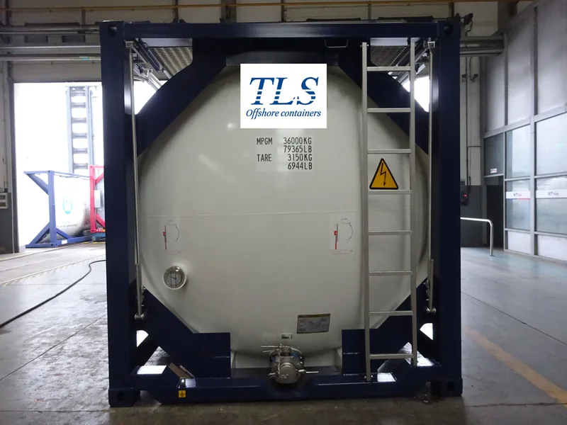
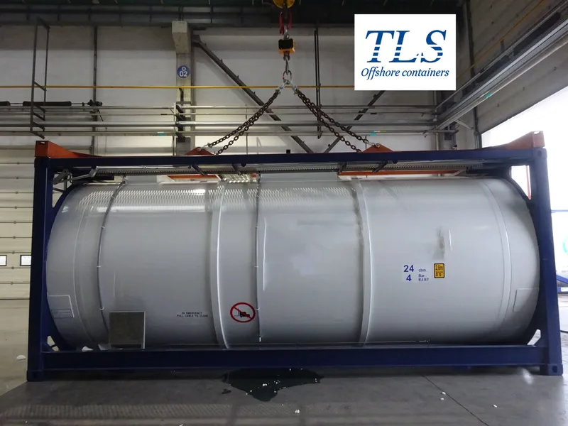
Tank containers are typically constructed using high-strength stainless steel (such as 304L or 316L) to ensure excellent corrosion resistance and mechanical strength. The external frame is designed according to ISO standards, providing robust impact resistance during transportation.
2.2 Explosion and Leak Prevention
To mitigate explosion risks, tank containers are equipped with various safety features:
- Pressure Relief Valves (PRV): Automatically release excess gas when internal pressure exceeds safe limits, preventing tank rupture.
- Inert Gas Filling: For flammable liquids, nitrogen gas is often used to reduce oxygen concentration and minimize explosion risks.
- Double-Wall Tank Design: Some high-safety applications utilize double-layer tanks for additional leak protection.
3. Overview of Other Key Aspects
3.1 Applications
Tank containers are widely used in the petroleum and chemical industries, and their demand is increasing in the energy sector, including liquid hydrogen and LNG. Compared to fixed storage tanks, tank containers offer greater flexibility and mobility, making them ideal for emergency supply chain management.
3.2 Market Trends
With the rising demand for hazardous material transportation, the market for high-safety tank containers is expanding. Additionally, stricter environmental regulations are driving the adoption of recyclable and low-emission materials.
3.3 Technological Innovations
New materials, such as high-strength composites, and advanced monitoring technologies, such as remote pressure and temperature monitoring, are enhancing the safety and operational efficiency of tank containers.
4. Conclusion
Tank containers play an indispensable role in liquid transportation and storage. Their regulatory compliance ensures global transport safety, while continuous safety design improvements help mitigate risks. As market demand and technological advancements progress, tank containers will find increasing applications in emerging industries, moving towards greater efficiency and environmental sustainability.
TLS Offshore Containers / TLS Special Containers is a global supplier of standard and customised containerised solutions.
Wherever you are in the world TLS can help you, please contact us. For more detailed information on offshore tanks, please review the link:https://www.tls-containers.com/tankcontainer.html.
Keywords:#Tank Container,#Regulatory Compliance,#Safety Design,#IMO (International Maritime Organization),#DNV Certification,#ASME Standards,#Pressure Vessel,#Hazardous Material Transportation,#Leak Prevention,#Explosion Protection,#Pressure Relief Valve (PRV),#Inert Gas Filling,#Double-Wall Tank,#Market Trends,#Technological Innovation