DC fuses play a crucial role in protecting Battery Energy Storage Systems (BESS) from short-circuit and overcurrent faults. Unlike traditional AC systems, BESS presents unique challenges due to high DC voltages, rapid current rise times, and energy-intensive fault conditions. Therefore, selecting the right fuse based on core parameters is essential for system safety, longevity, and performance.
DC Fuse Types and Classification
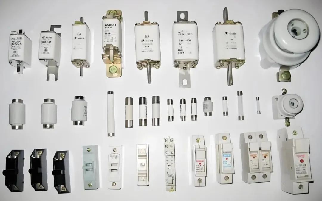
A DC fuse typically consists of a fusible element, quartz sand, and metal end caps. According to the GB13539.1-2015 standard, fuses are classified using a two-letter code. The first letter denotes the breaking range:
• “g” indicates full-range protection for overload and short-circuit conditions.
• “a” indicates partial-range protection (backup protection), which must be used with other devices.
The second letter indicates the application:
• “G” for general conductors,
• “M” for motor circuits,
• “R” for semiconductors.
For instance, a gG fuse provides full-range protection for general applications, while an aR fuse is ideal for fast protection of sensitive semiconductor components.
Key Parameters: Ft Value and Breaking Capacity
Three critical parameters define a DC fuse’s performance:
1. Rated current – the maximum continuous current the fuse can carry.
2. Breaking capacity – the highest fault current the fuse can safely interrupt.
3. Pre-arcing I²t (Ft value) – the energy the fuse can absorb before opening the circuit.
The Ft value is vital for ensuring selective coordination. In multi-stage protection systems, the downstream fuse must have a lower Ft value than the upstream fuse’s minimum pre-arcing Ft. This ensures only the nearest fuse to the fault operates, avoiding unnecessary power outages in other parts of the system.
For faults lasting less than 0.1 seconds, coordination must be verified by comparing Ft values. For faults over 0.1 seconds, the time-current characteristic curve is used to confirm selectivity.
Arc Quenching Process and Material Considerations
A fuse operates in four stages: heating, melting, arcing, and arc extinguishing. Once a fault occurs, the fusible link heats rapidly and melts, creating an arc. Quartz sand, filled around the fuse element, acts as an arc suppressor. It absorbs energy and forms a high-resistance “lava” layer that quenches the arc within milliseconds.
Factors like sand grain size and filling density directly affect quenching efficiency. Additionally, the fuse element material—commonly silver or copper—must balance conductivity, melting point, and cost for reliable performance at different voltage levels.
Fuse Application in BESS Systems
In large-scale BESS installations, short-circuit currents can exceed tens of kiloamperes. This requires fuses with very high breaking capacity, such as gR-type fuses.
Multiple fuse levels are often used in series—main circuit fuses with higher current ratings, and branch circuit fuses with faster response times. To maintain proper selectivity, Ft values between stages must differ by a factor of at least 1.5. In some designs, limiting reactors are added to reduce mutual inductance effects in parallel branches and assist in fault current limitation.
DC Fuse Types and Classification
A DC fuse typically consists of a fusible element, quartz sand, and metal end caps. According to the GB13539.1-2015 standard, fuses are classified using a two-letter code. The first letter denotes the breaking range:
• “g” indicates full-range protection for overload and short-circuit conditions.
• “a” indicates partial-range protection (backup protection), which must be used with other devices.
The second letter indicates the application:
• “G” for general conductors,
• “M” for motor circuits,
• “R” for semiconductors.
For instance, a gG fuse provides full-range protection for general applications, while an aR fuse is ideal for fast protection of sensitive semiconductor components.
Key Parameters: Ft Value and Breaking Capacity
Three critical parameters define a DC fuse’s performance:
1. Rated current – the maximum continuous current the fuse can carry.
2. Breaking capacity – the highest fault current the fuse can safely interrupt.
3. Pre-arcing I²t (Ft value) – the energy the fuse can absorb before opening the circuit.
The Ft value is vital for ensuring selective coordination. In multi-stage protection systems, the downstream fuse must have a lower Ft value than the upstream fuse’s minimum pre-arcing Ft. This ensures only the nearest fuse to the fault operates, avoiding unnecessary power outages in other parts of the system.
For faults lasting less than 0.1 seconds, coordination must be verified by comparing Ft values. For faults over 0.1 seconds, the time-current characteristic curve is used to confirm selectivity.
Arc Quenching Process and Material Considerations
A fuse operates in four stages: heating, melting, arcing, and arc extinguishing. Once a fault occurs, the fusible link heats rapidly and melts, creating an arc. Quartz sand, filled around the fuse element, acts as an arc suppressor. It absorbs energy and forms a high-resistance “lava” layer that quenches the arc within milliseconds.
Factors like sand grain size and filling density directly affect quenching efficiency. Additionally, the fuse element material—commonly silver or copper—must balance conductivity, melting point, and cost for reliable performance at different voltage levels.
Fuse Application in BESS Systems
In large-scale BESS installations, short-circuit currents can exceed tens of kiloamperes. This requires fuses with very high breaking capacity, such as gR-type fuses.
Multiple fuse levels are often used in series—main circuit fuses with higher current ratings, and branch circuit fuses with faster response times. To maintain proper selectivity, Ft values between stages must differ by a factor of at least 1.5. In some designs, limiting reactors are added to reduce mutual inductance effects in parallel branches and assist in fault current limitation.