- Published on
In demanding environments, especially offshore, safety and precision are paramount. TLS Offshore Containers offers cutting-edge Negative Pressure Laboratory Containers that provide a secure, self-contained, and highly customizable solution for critical testing and analysis.
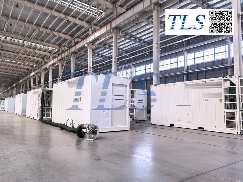
What is a Negative Pressure Laboratory Container?
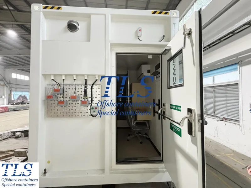
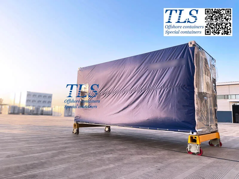
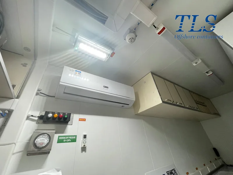
A negative pressure laboratory container is a self-contained, movable module designed to meet rigorous laboratory requirements. Its core principle is maintaining an internal pressure lower than the external environment. This crucial design feature ensures that air flows from the outside in, preventing the escape of harmful or flammable gases generated during operations. This makes them ideal for environments where hazardous substances are present or where precise environmental control is vital.
Unparalleled Safety Features for Demanding Environments
Safety is built into every TLS negative pressure lab container. Here's how:
Designed for Optimal Functionality and Convenience
TLS negative pressure laboratory containers are engineered for efficiency and ease of use:
1. Independent Operation: Each container is self-contained with its own compressed air, lighting, and ventilation systems.
2. Customization: Tailored to your specific needs, these labs can be customized in dimensions (10ft, 20ft, or custom) and internal layout.
3. Comprehensive Internal Fit-out:
Versatile Applications
These highly adaptable containers are suitable for various critical laboratory functions, including:
Your Global Partner in Containerized Solutions
TLS Offshore Containers is a global leading supplier of containerized solutions. Wherever your operations are located, TLS can provide the expertise and the right solution for you.
Contact TLS Offshore Containers today to discuss your specific requirements for a secure, efficient, and reliable negative pressure laboratory container solution.
TLS Offshore Containers / TLS Energy is a global supplier of standard and customised containerised solutions.
Wherever you are in the world TLS can help you, please contact us.
Please download Laboratory container brochure for reference.
Keywords: #Negative pressure lab container, #Portable laboratory solutions, #Offshore lab containers, #Containerized lab units, #Explosion-proof lab container, #Customizable lab container, #DNV2.7-1 certified container, #Modular petroleum laboratory, #Mobile laboratory cabin
What is a Negative Pressure Laboratory Container?
A negative pressure laboratory container is a self-contained, movable module designed to meet rigorous laboratory requirements. Its core principle is maintaining an internal pressure lower than the external environment. This crucial design feature ensures that air flows from the outside in, preventing the escape of harmful or flammable gases generated during operations. This makes them ideal for environments where hazardous substances are present or where precise environmental control is vital.
Unparalleled Safety Features for Demanding Environments
Safety is built into every TLS negative pressure lab container. Here's how:
- Hazardous Gas Containment: The negative pressure system actively discharges flammable and explosive gases, providing a secure internal operating environment.
- Explosion-Proof Facilities: Equipped with explosion-proof electrical facilities, these containers mitigate risks in volatile atmospheres.
- Fire Safety: Features like A0 or A60 fire ratings and autonomous fire, gas, and smoke detection systems offer robust protection.
- Extreme Weather Resilience: Fully insulated and built with materials that withstand temperatures from −20∘C to +60∘C, the containers maintain structural integrity and watertightness in harsh conditions.
- Compliance & Certification: Our containers are designed to meet stringent industry standards, including DNV2.7-1/EN12079 certification and CSC plating. Compliance with ATEX and IECEx standards is also available upon request.
Designed for Optimal Functionality and Convenience
TLS negative pressure laboratory containers are engineered for efficiency and ease of use:
1. Independent Operation: Each container is self-contained with its own compressed air, lighting, and ventilation systems.
2. Customization: Tailored to your specific needs, these labs can be customized in dimensions (10ft, 20ft, or custom) and internal layout.
3. Comprehensive Internal Fit-out:
- Self-contained Heat, Ventilation, and Air Conditioning (HVAC) system.
- Water supply system with connections to rig supply.
- Air pipeline connected with an air gun.
- Explosion-proof fume hood.
- Acid and alkali resistant anti-slip flooring and workbench.
- Work desk with phone, computer, and LAN connections.
- Working and storage furniture, including stainless steel sink units with raised edges and ample drainage.
- Eye washer.
- Under-bench and over-bench cabinets for storage of consumables.
- Ex light, switch, socket, and cabling.
Versatile Applications
These highly adaptable containers are suitable for various critical laboratory functions, including:
- Modular Petroleum Laboratory
- Mud Lab
- General cargo operations
- Road, rail, and sea transport (above or below deck)
Your Global Partner in Containerized Solutions
TLS Offshore Containers is a global leading supplier of containerized solutions. Wherever your operations are located, TLS can provide the expertise and the right solution for you.
Contact TLS Offshore Containers today to discuss your specific requirements for a secure, efficient, and reliable negative pressure laboratory container solution.
TLS Offshore Containers / TLS Energy is a global supplier of standard and customised containerised solutions.
Wherever you are in the world TLS can help you, please contact us.
Please download Laboratory container brochure for reference.
Keywords: #Negative pressure lab container, #Portable laboratory solutions, #Offshore lab containers, #Containerized lab units, #Explosion-proof lab container, #Customizable lab container, #DNV2.7-1 certified container, #Modular petroleum laboratory, #Mobile laboratory cabin
Written by Oliver
- Published on
Introduction
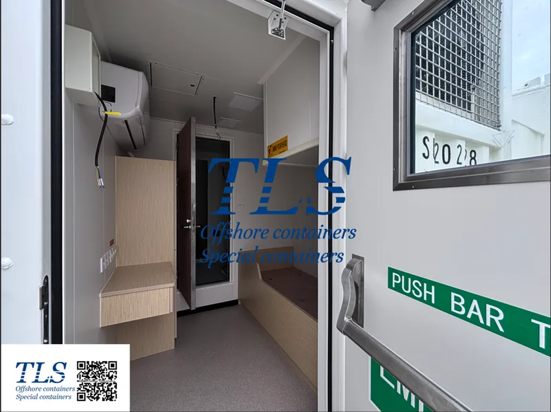
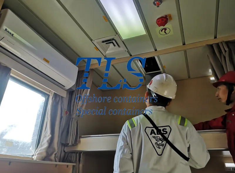
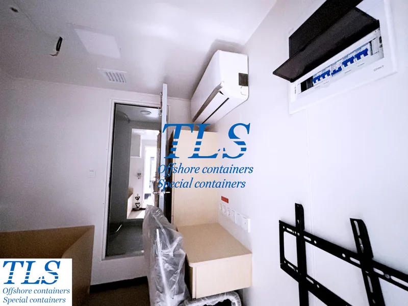
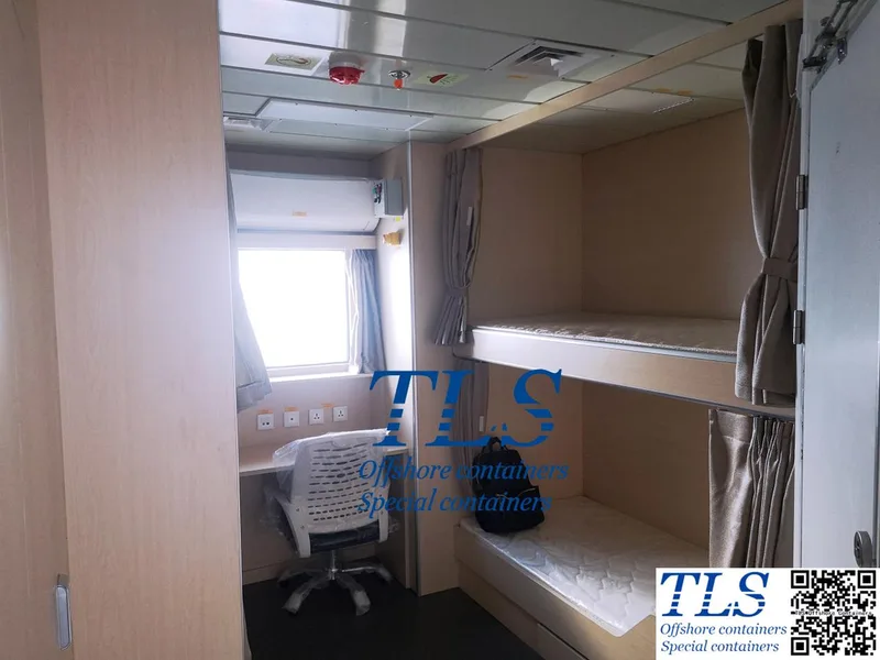
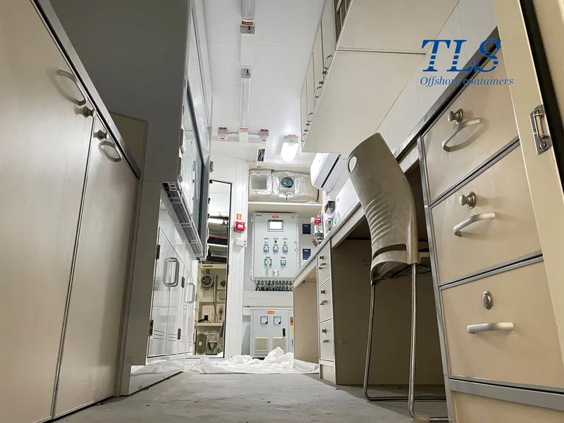
In the challenging world of offshore operations, providing safe, comfortable, and practical living spaces is essential. TLS, a trusted name in offshore containerized solutions, presents the 20ft Offshore Accommodation Cabin — a compact yet fully-equipped unit designed for personnel comfort and operational efficiency. Engineered for excellence, this cabin accommodates 2–4 people and redefines offshore living with its thoughtful layout, durable construction, and essential amenities.
Unveiling the TLS 20ft Offshore Accommodation Cabin
The TLS 20ft Accommodation Cabin is not just a place to stay — it's a purpose-built offshore home designed for durability, safety, and comfort. Every detail is crafted to enhance the living experience at sea or in remote offshore locations.
Key Features:
Versatile Applications in Offshore Environments
The adaptability of the TLS 20ft Accommodation Cabin makes it suitable for a wide range of offshore and nearshore uses:
Why Choose TLS Offshore Cabins?
With years of expertise in offshore engineering, TLS stands out for its commitment to safety, comfort, and customer-centric solutions. Our accommodation cabins are designed with feedback from real offshore users, ensuring every cabin meets the highest standards in the industry. From project-specific customization to global delivery, TLS delivers turnkey container solutions you can rely on.
Conclusion
The TLS 20ft Offshore Accommodation Cabin sets a new benchmark for offshore living. With its blend of ergonomic design, safety-focused features, and reliable performance, it ensures your crew stays comfortable and productive in any offshore condition. Whether you're managing an oil platform, leading a research expedition, or pioneering ocean-based tourism, TLS cabins deliver comfort you can count on.
TLS Offshore Containers / TLS Energy is a global supplier of standard and customised containerised solutions.
Wherever you are in the world TLS can help you, please contact us.
More information about accommodation modulars, offshore accommodation cabins, gallery module, mess module, etc. Please download TLS accommodation modular brochure , TLS ABS approved offshore accommodation module brochure for reference.
Keywords: #Offshore accommodation cabin, #20ft offshore living container, #TLS accommodation unit, #Containerized housing for oil platforms, #Marine accommodation container, #Portable offshore housing, #Modular living quarters for offshore
In the challenging world of offshore operations, providing safe, comfortable, and practical living spaces is essential. TLS, a trusted name in offshore containerized solutions, presents the 20ft Offshore Accommodation Cabin — a compact yet fully-equipped unit designed for personnel comfort and operational efficiency. Engineered for excellence, this cabin accommodates 2–4 people and redefines offshore living with its thoughtful layout, durable construction, and essential amenities.
Unveiling the TLS 20ft Offshore Accommodation Cabin
The TLS 20ft Accommodation Cabin is not just a place to stay — it's a purpose-built offshore home designed for durability, safety, and comfort. Every detail is crafted to enhance the living experience at sea or in remote offshore locations.
Key Features:
- Spacious Layout
- Essential Amenities
- Robust Construction
- Advanced Safety Features
- Energy-Efficient Design
Versatile Applications in Offshore Environments
The adaptability of the TLS 20ft Accommodation Cabin makes it suitable for a wide range of offshore and nearshore uses:
- Oil & Gas Platforms
- Marine Research Missions
- Aquaculture Operations
- Eco-Tourism & Leisure
Why Choose TLS Offshore Cabins?
With years of expertise in offshore engineering, TLS stands out for its commitment to safety, comfort, and customer-centric solutions. Our accommodation cabins are designed with feedback from real offshore users, ensuring every cabin meets the highest standards in the industry. From project-specific customization to global delivery, TLS delivers turnkey container solutions you can rely on.
Conclusion
The TLS 20ft Offshore Accommodation Cabin sets a new benchmark for offshore living. With its blend of ergonomic design, safety-focused features, and reliable performance, it ensures your crew stays comfortable and productive in any offshore condition. Whether you're managing an oil platform, leading a research expedition, or pioneering ocean-based tourism, TLS cabins deliver comfort you can count on.
TLS Offshore Containers / TLS Energy is a global supplier of standard and customised containerised solutions.
Wherever you are in the world TLS can help you, please contact us.
More information about accommodation modulars, offshore accommodation cabins, gallery module, mess module, etc. Please download TLS accommodation modular brochure , TLS ABS approved offshore accommodation module brochure for reference.
Keywords: #Offshore accommodation cabin, #20ft offshore living container, #TLS accommodation unit, #Containerized housing for oil platforms, #Marine accommodation container, #Portable offshore housing, #Modular living quarters for offshore
Written by Oliver
- Published on
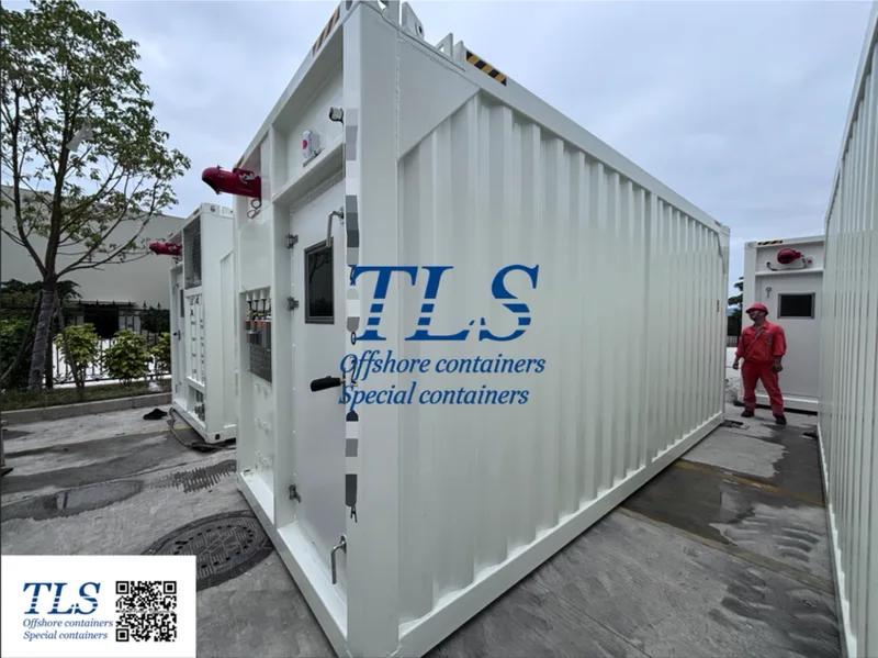
In hazardous environments, especially within the oil, gas, and renewable energy industries, safety and reliable operations are paramount. TLS Offshore Containers Int. stands as a global leader, providing cutting-edge containerized solutions, including their specialized Total Pressurized Container Solutions.
What are Pressurized Containers and Why Are They Crucial?
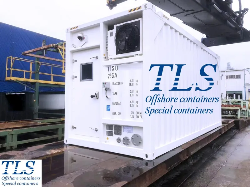
Pressurized containers, often referred to as cabins, are designed to create a safe working environment in areas where flammable gases, vapors, or combustible dust may be present (Zone 1/Zone 2 hazardous areas). By maintaining a positive internal pressure, these units prevent the ingress of hazardous external atmospheres, protecting personnel and sensitive equipment. This makes them indispensable for critical operations in demanding offshore and onshore settings.
TLS: Decades of Expertise in Hazardous Environments
With manufacturing experience for the Oil and Gas industry since 1998, TLS has a proven track record of delivering robust and reliable solutions. Their in-house engineering team is equipped to provide complete, customized solutions tailored to specific project requirements.
Key Applications of TLS Pressurized Container Solutions
TLS offers a diverse range of customized pressurized units, including:
Uncompromising Standards and Specifications
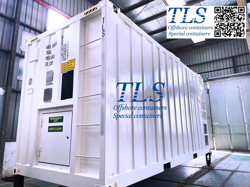
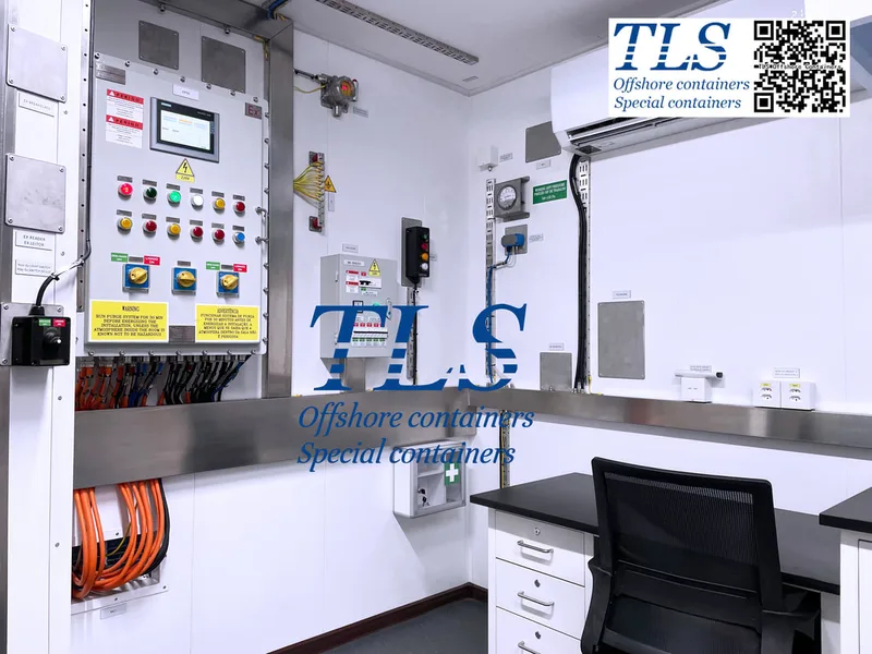
TLS pressurized containers, such as their Mud Logging Cabins, are built to the highest international standards, ensuring peak performance and safety. Key specifications include:
Global Reach and Support
TLS Offshore Containers Int. is committed to supporting clients worldwide. With offices in Singapore and China, they are well-positioned to serve the global market.
For more information on TLS Total Pressurized Container Solutions and how they can enhance the safety and efficiency of your operations in hazardous environments, contact TLS Offshore Containers Int. today.
TLS Offshore Containers / TLS Energy is a global supplier of standard and customised containerised solutions.
Wherever you are in the world TLS can help you, please contact us.
Product brochures:
Offshore pressurised mud logging cabin brochure
MCC | Switchgear | VFD | VSD pressurised shelter
Keywords: #Pressurized containers, #Offshore containers, #Hazardous area cabins, #DNV 2.7-1 certified containers, #A60 rated cabins, #Mud logging cabin specifications, #Zone 1 Zone 2 cabins, #Oil and gas containers, #Renewable energy containers, #Containerized solutions supplier
What are Pressurized Containers and Why Are They Crucial?
Pressurized containers, often referred to as cabins, are designed to create a safe working environment in areas where flammable gases, vapors, or combustible dust may be present (Zone 1/Zone 2 hazardous areas). By maintaining a positive internal pressure, these units prevent the ingress of hazardous external atmospheres, protecting personnel and sensitive equipment. This makes them indispensable for critical operations in demanding offshore and onshore settings.
TLS: Decades of Expertise in Hazardous Environments
With manufacturing experience for the Oil and Gas industry since 1998, TLS has a proven track record of delivering robust and reliable solutions. Their in-house engineering team is equipped to provide complete, customized solutions tailored to specific project requirements.
Key Applications of TLS Pressurized Container Solutions
TLS offers a diverse range of customized pressurized units, including:
- ROV Cabins: For controlling Remotely Operated Vehicles.
- Test Cabins: Providing a controlled environment for equipment testing.
- Control Cabins: Housing vital control systems.
- Telecommunications Cabins: Protecting communication infrastructure.
- MWD/LWD Cabins: Essential for Measurement While Drilling/Logging While Drilling operations.
- Office Cabins: Safe and functional workspaces.
- Laboratory Cabins: For on-site analysis and research.
- Mud Logging Cabins: Critical for well logging operations.
Uncompromising Standards and Specifications
TLS pressurized containers, such as their Mud Logging Cabins, are built to the highest international standards, ensuring peak performance and safety. Key specifications include:
- A60 Fire Rating: Walls, roof, and floor are A60 rated for superior fire protection.
- Structural Integrity: Designed, manufactured, and certified to DNV 2.7-1/EN12079 standards, ensuring durability and safety for offshore applications.
- Hazardous Area Compliance: Conforming to Zone 1 and Zone 2 classifications.
- Integrated Safety Systems: Equipped with comprehensive Fire, Gas, and Smoke Safety Systems, including fire and gas detectors, and H2S detectors.
- Advanced HVAC: Featuring 24000 BTU/Hr split-type air conditioning suitable for hazardous area applications.
- Robust Electrical Systems: Including a 20KVA transformer and essential electrical panels, lighting, and safety switches.
- Quality Construction: Internal roof finished with powder-coated GI sheet, walls with 25mm thick sandwich panels, and 2mm thick vinyl mat flooring.
- Comprehensive Detection and Alarm System: A Combined Pressurization on Fire and Gas (CPFG) detection panel for Zone 1, integrating gas detection (H2S and CH4), smoke detection, emergency stop, pressurization fan, and alarms.
- Certification: All products are produced to international standards and meet ISO1496/CSC, ISO 14001:2015, ISO900, Type Approval CSC-International, and Type Approval SOLAS A60.
Global Reach and Support
TLS Offshore Containers Int. is committed to supporting clients worldwide. With offices in Singapore and China, they are well-positioned to serve the global market.
For more information on TLS Total Pressurized Container Solutions and how they can enhance the safety and efficiency of your operations in hazardous environments, contact TLS Offshore Containers Int. today.
TLS Offshore Containers / TLS Energy is a global supplier of standard and customised containerised solutions.
Wherever you are in the world TLS can help you, please contact us.
Product brochures:
Offshore pressurised mud logging cabin brochure
MCC | Switchgear | VFD | VSD pressurised shelter
Keywords: #Pressurized containers, #Offshore containers, #Hazardous area cabins, #DNV 2.7-1 certified containers, #A60 rated cabins, #Mud logging cabin specifications, #Zone 1 Zone 2 cabins, #Oil and gas containers, #Renewable energy containers, #Containerized solutions supplier
Written by Oliver
- Published on
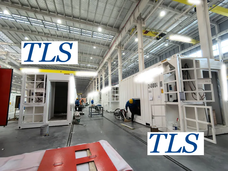
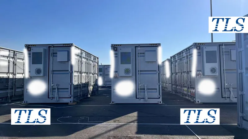
In temporary project sites such as field exploration, energy development, and construction, accommodation is a critical aspect of logistical support. TLS specializes in designing and manufacturing custom functional containers, with accommodation containers being one of our most high-demand products. With their superior structural strength, high comfort levels, and a high degree of integration, these containers are favored by overseas clients, EPC contractors, and general engineering contractors.
This article provides an in-depth overview of TLS accommodation containers, covering their structural design, electrical configuration, thermal performance, and human-centered layout features, showcasing the advantages they bring to high-standard accommodation projects.
1. Structural Design: Suited for Lifting, Modular Assembly, and Harsh Weather Conditions
TLS accommodation containers are built using standard container frame structures, which provide excellent mechanical strength and mobility. These designs meet the following requirements:
The frame is typically made from weather-resistant steel and coated with marine-grade corrosion protection to ensure long-lasting performance in environments like coastal areas, deserts, and high-altitude regions.
2. Insulation, Thermal, and Acoustic Design: Enhancing Comfort for Occupants
The walls and ceiling of the accommodation container are usually equipped with 50-100mm thick rock wool insulation, offering excellent thermal performance suitable for multiple climate zones. The window and door systems feature:
Internally, eco-friendly PVC cladding is commonly used for the walls, providing fire resistance, mold prevention, and easy cleaning.
3. Electrical System: Integrated Lighting, Air Conditioning, and Electrical Safety
Before delivery, the accommodation container is pre-installed with a fully functional electrical system, ensuring plug-and-play capability:
All systems comply with IEC, GB, or customer-specific electrical standards and are CE or ATEX-compliant for hazardous areas (upon request).
4. Integrated Sanitary Features: Self-contained Living Units with Bathroom Configurations
Some accommodation containers are designed with integrated bathroom modules, providing full living functionality. Features include:
This configuration is ideal for management units, on-site stations, and shift workers needing complete privacy and comfort.
5. Customization Options and Delivery Packages
TLS offers customized configurations based on the specific needs of a project’s site, including:
Conclusion:
As an essential component of project site infrastructure, container-based accommodation modules are gradually replacing traditional temporary buildings, providing a more efficient, safe, and recyclable living solution for workers.
With years of expertise in custom container manufacturing, TLS offers high-quality accommodation containers for global clients, supporting bulk deliveries, international certifications, cross-border transport, and local adaptability.
TLS Offshore Containers / TLS Energy is a global supplier of standard and customised containerised solutions.
Wherever you are in the world TLS can help you, please contact us.
Keywords:#Custom accommodation containers,#Temporary housing solutions,#Modular container housing,#Containerized accommodation,#Mobile living units,#EPC contractors,#Harsh environment living solutions,#Energy-efficient accommodation,#Container accommodation modules,#Portable living spaces,#Insulated containers,#On-site worker housing,#Integrated electrical systems,#Containerized bathrooms#Solar-powered accommodation
This article provides an in-depth overview of TLS accommodation containers, covering their structural design, electrical configuration, thermal performance, and human-centered layout features, showcasing the advantages they bring to high-standard accommodation projects.
1. Structural Design: Suited for Lifting, Modular Assembly, and Harsh Weather Conditions
TLS accommodation containers are built using standard container frame structures, which provide excellent mechanical strength and mobility. These designs meet the following requirements:
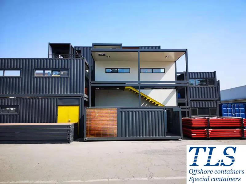
- Environments requiring frequent lifting and transportation (e.g., construction sites)
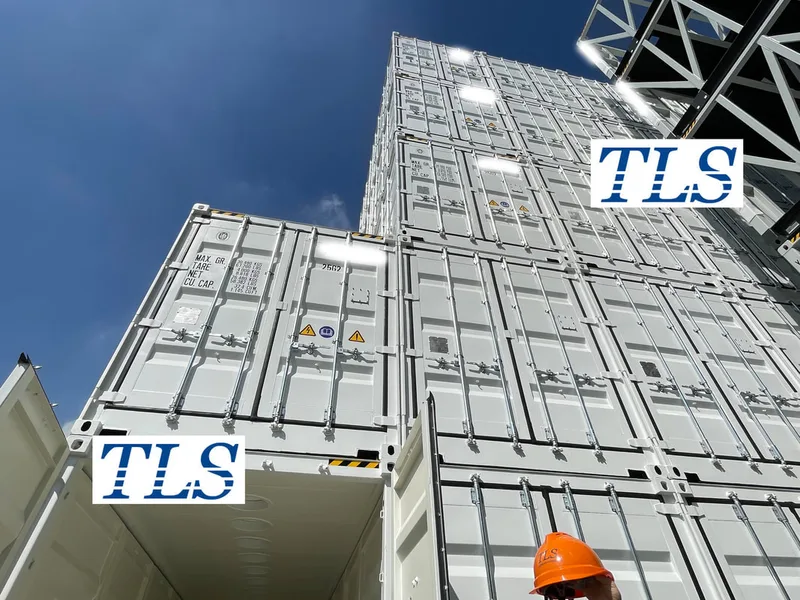
- Modular camp layouts, including stacked configurations (such as single or two-story designs)
- Resilience in extreme weather conditions like high temperatures, high humidity, and dust storms
- Quick deployment and overall recyclability
The frame is typically made from weather-resistant steel and coated with marine-grade corrosion protection to ensure long-lasting performance in environments like coastal areas, deserts, and high-altitude regions.
2. Insulation, Thermal, and Acoustic Design: Enhancing Comfort for Occupants
The walls and ceiling of the accommodation container are usually equipped with 50-100mm thick rock wool insulation, offering excellent thermal performance suitable for multiple climate zones. The window and door systems feature:
- Plastic steel frames with double-glazed windows
- Optional external-opening windows with mosquito screens for ventilation and insect protection
Internally, eco-friendly PVC cladding is commonly used for the walls, providing fire resistance, mold prevention, and easy cleaning.
3. Electrical System: Integrated Lighting, Air Conditioning, and Electrical Safety
Before delivery, the accommodation container is pre-installed with a fully functional electrical system, ensuring plug-and-play capability:
- LED lighting, power outlets, air conditioning outlets, and water heater circuits
- Pre-installed circuit breakers, leakage protection, and overload protection
- Electrical input/output ports designed to match the client’s on-site power supply (bottom or side cable entry)
All systems comply with IEC, GB, or customer-specific electrical standards and are CE or ATEX-compliant for hazardous areas (upon request).
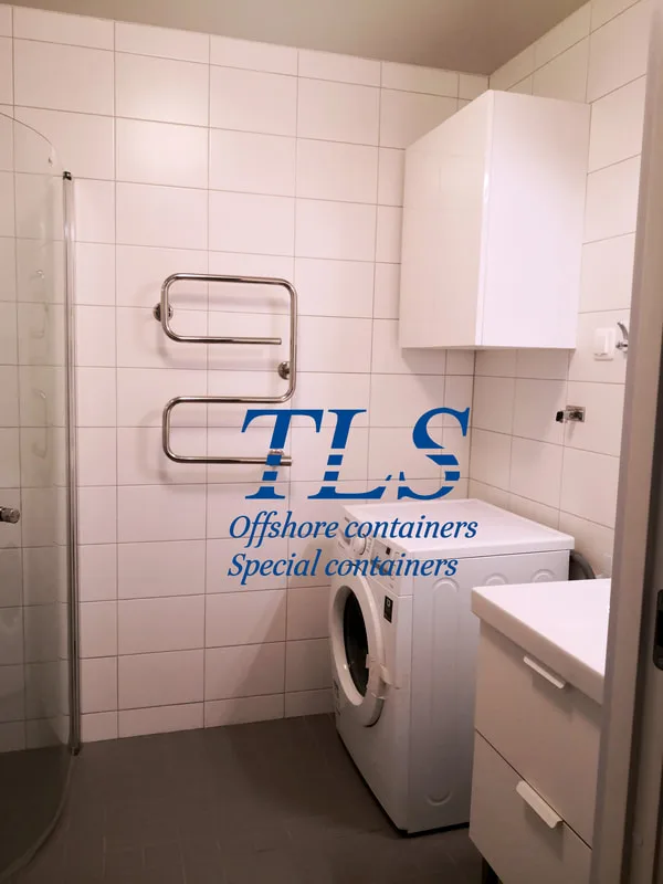
4. Integrated Sanitary Features: Self-contained Living Units with Bathroom Configurations
Some accommodation containers are designed with integrated bathroom modules, providing full living functionality. Features include:
- Shower, toilet, washbasin, and ventilation fan
- Wastewater drainage system with provisions for freshwater and wastewater storage
- Electric water heater and lighting control system
This configuration is ideal for management units, on-site stations, and shift workers needing complete privacy and comfort.
5. Customization Options and Delivery Packages
TLS offers customized configurations based on the specific needs of a project’s site, including:
- Single, double, or multi-occupancy layouts
- Custom exterior painting, including logos, numbering, and equipment identification plates
- Integration with communication, security, energy storage, solar power, and other systems for turnkey delivery
Conclusion:
As an essential component of project site infrastructure, container-based accommodation modules are gradually replacing traditional temporary buildings, providing a more efficient, safe, and recyclable living solution for workers.
With years of expertise in custom container manufacturing, TLS offers high-quality accommodation containers for global clients, supporting bulk deliveries, international certifications, cross-border transport, and local adaptability.
TLS Offshore Containers / TLS Energy is a global supplier of standard and customised containerised solutions.
Wherever you are in the world TLS can help you, please contact us.
Keywords:#Custom accommodation containers,#Temporary housing solutions,#Modular container housing,#Containerized accommodation,#Mobile living units,#EPC contractors,#Harsh environment living solutions,#Energy-efficient accommodation,#Container accommodation modules,#Portable living spaces,#Insulated containers,#On-site worker housing,#Integrated electrical systems,#Containerized bathrooms#Solar-powered accommodation
Written by Snowy
- Published on
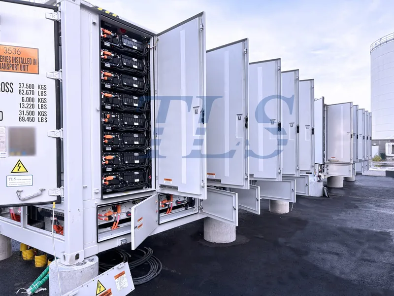
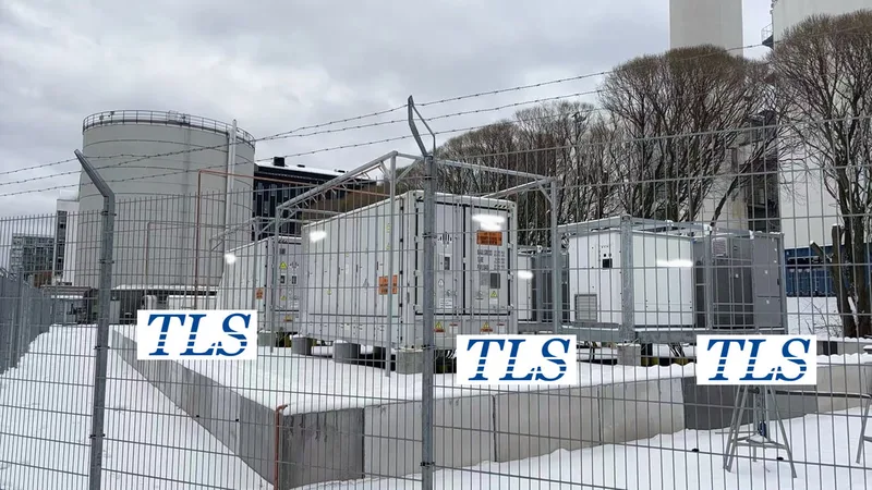
As the global installed capacity of renewable energy continues to surge, energy storage systems have become a critical pillar for ensuring power grid stability and flexibility. Among the various forms of energy storage, containerized battery energy storage systems (BESS) are gaining popularity worldwide due to their modular deployment, high integration, and rapid commissioning.
However, for procurement teams—especially within government or utility-scale projects—technical sophistication alone is not enough. What truly determines purchasing decisions is whether the system is safe, compliant with international standards, and capable of being delivered and operated legally and reliably.
1. Safety First—The Baseline of All Energy Storage
By nature, energy storage systems are high-energy-density installations. Their safety directly affects public infrastructure and personnel wellbeing. For lithium-based systems in particular, the risks of thermal runaway, internal short circuits, or battery cell damage leading to fire must be addressed proactively.
At TLS, our containerized BESS are designed with multi-layered safety mechanisms:
2. Compliance: The Passport to International Markets
For energy storage systems intended for government procurement and large-scale deployment, international certifications are not optional—they are essential. These certifications serve as both regulatory requirements and endorsements of quality and safety.
TLS energy storage containers adhere to globally recognized standards, including:
To ensure electromagnetic compatibility, TLS systems comply with the EN61000 series, and they have undergone rigorous environmental tests to confirm performance under extreme heat, humidity, dust, and salt spray conditions. For offshore and port-side applications, TLS can also support classification society certifications such as DNV, BV, and CCS.
These certifications not only validate TLS’s ability to deliver globally but also simplify regulatory approvals and reduce procurement risk for government buyers.
3. End-to-End Delivery Support for Complex Projects
Procurement for large-scale energy projects is often complex and time-consuming. TLS understands this deeply. That’s why we don’t just deliver certified products—we also provide full-spectrum support throughout the entire delivery cycle.
Each TLS energy storage project includes:
4. Conclusion: Compliance as the Bridge to Global Deployment
Energy storage is more than just a hardware purchase—it’s a strategic investment in national grid stability, public power safety, and long-term energy transformation. And at the core of any successful deployment lies one foundational principle: compliance.
TLS is committed to safety-first, standards-driven design and manufacturing. We aim to provide containerized BESS solutions that meet regulatory requirements across geographies, stand the test of time and environment, and help global partners realize secure, future-proof energy infrastructure.
TLS Offshore Containers / TLS Energy is a global supplier of standard and customised containerised solutions.
Wherever you are in the world TLS can help you, please contact us.
Keywords:#Energy Storage System,#Containerized BESS,#Battery Safety,#Thermal Runaway Protection,#Battery Management System (BMS),#UL 9540 Certification,#International Compliance,#Modular Energy Storage,#Fire Suppression System,#Renewable Energy Integration,#Grid Stability,#Global Energy Markets,#Offshore Energy Storage,#CE and UKCA Marking,#Turnkey Energy Solutions,
However, for procurement teams—especially within government or utility-scale projects—technical sophistication alone is not enough. What truly determines purchasing decisions is whether the system is safe, compliant with international standards, and capable of being delivered and operated legally and reliably.
1. Safety First—The Baseline of All Energy Storage
By nature, energy storage systems are high-energy-density installations. Their safety directly affects public infrastructure and personnel wellbeing. For lithium-based systems in particular, the risks of thermal runaway, internal short circuits, or battery cell damage leading to fire must be addressed proactively.
At TLS, our containerized BESS are designed with multi-layered safety mechanisms:
- Each system is equipped with an independent Battery Management System (BMS) that continuously monitors voltage, temperature, and charge/discharge status, enabling early warnings of any potential hazards.
- Advanced fire protection systems can be integrated, featuring smoke and heat detectors alongside gas-based fire suppression, ensuring localized fire control and ventilation system coordination in the event of an incident.
- The container’s structural design offers dustproof, waterproof, and corrosion-resistant performance, making it suitable for deployment in harsh environments and supporting long-term asset lifecycle management for operators and government agencies.
2. Compliance: The Passport to International Markets
For energy storage systems intended for government procurement and large-scale deployment, international certifications are not optional—they are essential. These certifications serve as both regulatory requirements and endorsements of quality and safety.
TLS energy storage containers adhere to globally recognized standards, including:
- UL 9540 and IEC 62933 for system-level safety evaluations
- UL 9540A for thermal runaway fire propagation testing
- UN 38.3 for transport safety of lithium battery cells and modules
- CE and UKCA certifications for European and UK market entry
To ensure electromagnetic compatibility, TLS systems comply with the EN61000 series, and they have undergone rigorous environmental tests to confirm performance under extreme heat, humidity, dust, and salt spray conditions. For offshore and port-side applications, TLS can also support classification society certifications such as DNV, BV, and CCS.
These certifications not only validate TLS’s ability to deliver globally but also simplify regulatory approvals and reduce procurement risk for government buyers.
3. End-to-End Delivery Support for Complex Projects
Procurement for large-scale energy projects is often complex and time-consuming. TLS understands this deeply. That’s why we don’t just deliver certified products—we also provide full-spectrum support throughout the entire delivery cycle.
Each TLS energy storage project includes:
- Complete documentation: certification dossiers, third-party test reports, safety data sheets, and operation manuals.
- Support for localized compliance applications: we assist clients with obtaining UKCA (UK), CSA (Canada), SASO (Saudi Arabia), and other regional certifications.
- Post-delivery services: local commissioning, on-site training, and remote monitoring system integration, ensuring the energy storage asset is truly deployable, maintainable, and manageable.
4. Conclusion: Compliance as the Bridge to Global Deployment
Energy storage is more than just a hardware purchase—it’s a strategic investment in national grid stability, public power safety, and long-term energy transformation. And at the core of any successful deployment lies one foundational principle: compliance.
TLS is committed to safety-first, standards-driven design and manufacturing. We aim to provide containerized BESS solutions that meet regulatory requirements across geographies, stand the test of time and environment, and help global partners realize secure, future-proof energy infrastructure.
TLS Offshore Containers / TLS Energy is a global supplier of standard and customised containerised solutions.
Wherever you are in the world TLS can help you, please contact us.
Keywords:#Energy Storage System,#Containerized BESS,#Battery Safety,#Thermal Runaway Protection,#Battery Management System (BMS),#UL 9540 Certification,#International Compliance,#Modular Energy Storage,#Fire Suppression System,#Renewable Energy Integration,#Grid Stability,#Global Energy Markets,#Offshore Energy Storage,#CE and UKCA Marking,#Turnkey Energy Solutions,
Written by Snowy
- Published on
In high-risk experimental environments involving hazardous chemicals, flammable gases, or explosive dust, positive pressure lab containers have become the go-to choice for research institutions, inspection units, and industrial lab projects. With their safety, stability, and controllability, these units offer a critical safeguard for personnel and processes.
However, a positive pressure lab container that’s truly “ready for use” is far more than just a fan installed in a steel shell. Its safety and performance hinge on the detailed engineering and quality behind every structural element.
At TLS, a specialized manufacturer of functional container systems, we have identified five key structural features that determine whether a positive pressure lab container is truly usable, reliable, and deliverable.
1. Airtight Structure – The Foundation of Everything
The primary requirement of a positive pressure lab container is the ability to maintain a stable internal pressure. This demands a high level of airtightness. TLS ensures this through:
2. Ventilation Interface and Air Duct Design
The direction of the air ducts and the location of the ventilation connections need to be determined at the design and manufacturing stage of the box, which plays a decisive role in the performance of the entire ventilation system.
TLS provides:
3. Explosion-Proof Electrical Interfaces and Cable Routing
For lab containers intended for Zone 1 or Zone 2 hazardous areas, the container must integrate with explosion-proof systems. TLS supports this by:
4. Safety Monitoring and System Compatibility
Safety monitoring is a key consideration in our lab container designs. Depending on client needs, we offer:
5. Customizable Modular Design
TLS lab containers feature a high degree of modularity, allowing flexible configuration based on project requirements:
Conclusion
A positive pressure lab container is not just a sealed box—it’s a carefully engineered system that integrates airtight construction, ventilation planning, electrical safety, monitoring readiness, and modular design.
TLS is dedicated to the development and manufacturing of functional containers and explosion-proof safety modules. With extensive industry experience, we work closely with clients to deliver high-standard lab environments that are safe, tailored, and field-ready.
TLS Offshore Containers / TLS Energy is a global supplier of standard and customised containerised solutions.
Wherever you are in the world TLS can help you, please contact us.
Keywords:#Positive pressure lab container,#Airtight enclosure,#Hazardous material testing,#Explosion-proof design,#Zone 1 Zone 2 compliance,#Modular lab unit,#Ventilation interface,#Industrial lab safety,#Pressurized laboratory container,#Custom container solutions,#IECEx compliant,#Functional container manufacturer,#Containment system,#Safe lab environment,#Lab container integration
However, a positive pressure lab container that’s truly “ready for use” is far more than just a fan installed in a steel shell. Its safety and performance hinge on the detailed engineering and quality behind every structural element.
At TLS, a specialized manufacturer of functional container systems, we have identified five key structural features that determine whether a positive pressure lab container is truly usable, reliable, and deliverable.
1. Airtight Structure – The Foundation of Everything
The primary requirement of a positive pressure lab container is the ability to maintain a stable internal pressure. This demands a high level of airtightness. TLS ensures this through:
- Double-layer sealing strips on doors for enhanced closure tightness
- Airtight cable gland systems at pipe entry points
- Full-welded seams with thorough inspection and repair to eliminate leaks
- Reinforced sealing components on doors, hatches, and viewing windows
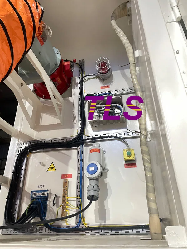
2. Ventilation Interface and Air Duct Design
The direction of the air ducts and the location of the ventilation connections need to be determined at the design and manufacturing stage of the box, which plays a decisive role in the performance of the entire ventilation system.
TLS provides:
- Standard or customized ducting interfaces (supporting top-down, side-top, or other configurations)
- Optimized internal air paths based on airflow volume and pressure specifications
- Well-planned duct layouts that improve system stability, prevent uneven airflow, and reduce the risk of equipment overload or dead zones
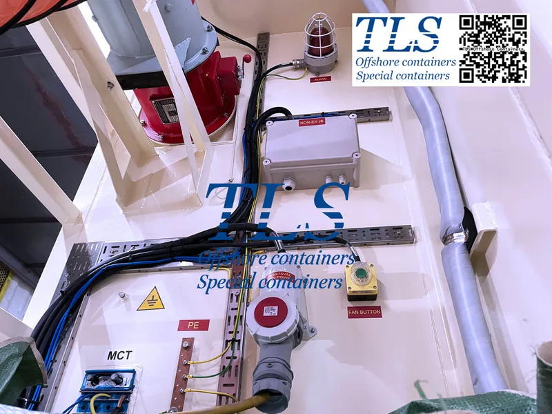
3. Explosion-Proof Electrical Interfaces and Cable Routing
For lab containers intended for Zone 1 or Zone 2 hazardous areas, the container must integrate with explosion-proof systems. TLS supports this by:
- Providing cable entry fittings compliant with Ex e or Ex d standards
- Pre-installing or reserving mounting supports for explosion-proof lighting, distribution boxes, and control panels
- Pre-routing cable trays and electrical paths based on customer drawings
- Ensuring internal wiring follows IECEx structural guidelines, making on-site integration fast and compliant
4. Safety Monitoring and System Compatibility
Safety monitoring is a key consideration in our lab container designs. Depending on client needs, we offer:
- Sensor installation ports: The system is equipped with smoke sensors, differential pressure sensors and temperature sensors to achieve safety monitoring and environmental linkage control. In response to customers' personalized demands, we can also reserve additional sensor installation holes as required to facilitate future expansion and functional upgrades.
- Cooperation on safety device integration: Our team actively assists with the installation of emergency stop buttons, audible/visual alarms, and fire suppression systems
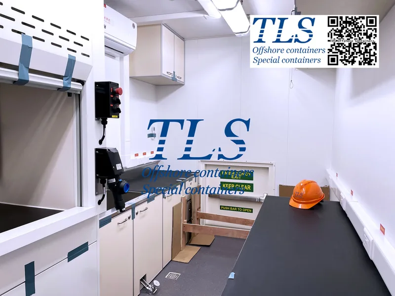
5. Customizable Modular Design
TLS lab containers feature a high degree of modularity, allowing flexible configuration based on project requirements:
- Dimensions can follow standard ISO footprints (10ft/20ft/40ft) or be fully customized
- Options to add observation windows, access doors, and maintenance hatches
- Support for multi-container linkage and rapid field deployment through modular connections
Conclusion
A positive pressure lab container is not just a sealed box—it’s a carefully engineered system that integrates airtight construction, ventilation planning, electrical safety, monitoring readiness, and modular design.
TLS is dedicated to the development and manufacturing of functional containers and explosion-proof safety modules. With extensive industry experience, we work closely with clients to deliver high-standard lab environments that are safe, tailored, and field-ready.
TLS Offshore Containers / TLS Energy is a global supplier of standard and customised containerised solutions.
Wherever you are in the world TLS can help you, please contact us.
Keywords:#Positive pressure lab container,#Airtight enclosure,#Hazardous material testing,#Explosion-proof design,#Zone 1 Zone 2 compliance,#Modular lab unit,#Ventilation interface,#Industrial lab safety,#Pressurized laboratory container,#Custom container solutions,#IECEx compliant,#Functional container manufacturer,#Containment system,#Safe lab environment,#Lab container integration
Write by Snowy
- Published on
Energy storage systems (ESS) are revolutionizing, how we store and manage energy, supporting renewable energy integration, grid stability, and sustainable power solutions. However, navigating the technical jargon of ESS can be daunting. This article breaks down the most common professional terms and their definitions, offering insights into their significance and practical considerations. Whether you're a professional in the energy sector or a curious enthusiast, this guide will clarify critical concepts like BMS, SOC, SOH, DOD, C-Rate, and cycle life.
1. Battery Management System (BMS)The Battery Management System (BMS) is the "brain" of an energy storage system. It monitors and manages battery performance, ensuring safety, efficiency, and longevity. The BMS oversees real-time monitoring, energy management, communication, diagnostics, safety protection, and cell balancing.
Key Points:
2. State of Charge (SOC)The State of Charge (SOC) represents the remaining battery capacity as a percentage of its rated capacity, calculated as SOC = (Remaining Capacity / Rated Capacity) × 100%. Think of it as the "fuel gauge" for a battery.
Key Points:
3. State of Health (SOH)The State of Health (SOH) measures a battery's current capacity relative to its initial rated capacity, expressed as SOH = (Current Actual Capacity / Initial Rated Capacity) × 100%. It indicates how much a battery has degraded over time.
Key Points:
4. Depth of Discharge (DOD)The Depth of Discharge (DOD) measures the percentage of a battery's rated capacity that has been discharged, calculated as DOD = (Discharged Capacity / Rated Capacity) × 100%.
Key Points:
5. C-Rate (Charge/Discharge Rate)The C-Rate describes the rate at which a battery is charged or discharged relative to its rated capacity. For example, a 0.5C rate means charging or discharging at half the battery's capacity.
Key Points:
6. Cycle LifeCycle life refers to the number of complete charge-discharge cycles a battery can undergo before its capacity degrades to a specified level (e.g., SOH of 70% or 80%). It’s a critical indicator of an ESS's longevity.
Key Considerations:
7. Battery Management Unit (BMU)The Battery Management Unit (BMU) is a component within the battery pack, responsible for collecting data on individual cell voltages and temperatures and executing cell balancing strategies.
Key Points:
8. Battery Cluster Management Unit (BCMU)The Battery Cluster Management Unit (BCMU), also known as BCU or ESBCM, collects data from BMUs, monitors cluster-level voltage, current, and insulation, and controls protective contactors.
Key Points:
9. Battery Stack Management Unit (BSMU)The Battery Stack Management Unit (BSMU), also called BSU, ESMU, BAMS, or BAU, manages data from BCMUs, stores and displays information, provides real-time alerts, and communicates with power conversion systems (PCS), energy management systems (EMS), and local monitoring systems.
Key Points:
Why Understanding These Terms MattersFor professionals and consumers alike, mastering these terms is essential for evaluating energy storage systems. Misleading claims about cycle life or performance metrics can lead to costly mistakes. By understanding BMS, SOC, SOH, DOD, C-Rate, and cycle life, you can make informed decisions, negotiate clear warranty terms, and ensure the system meets your needs.
Practical Tips:
1. Battery Management System (BMS)The Battery Management System (BMS) is the "brain" of an energy storage system. It monitors and manages battery performance, ensuring safety, efficiency, and longevity. The BMS oversees real-time monitoring, energy management, communication, diagnostics, safety protection, and cell balancing.
Key Points:
- Components: Comprises hardware (sensors, controllers) and software (algorithms for data processing).
- Importance: The BMS directly influences the system's safety, reliability, and cost-effectiveness. A robust BMS prevents overcharging, overheating, and other risks, extending battery life.
2. State of Charge (SOC)The State of Charge (SOC) represents the remaining battery capacity as a percentage of its rated capacity, calculated as SOC = (Remaining Capacity / Rated Capacity) × 100%. Think of it as the "fuel gauge" for a battery.
Key Points:
- Role: SOC is critical for BMS protection mechanisms, charge-discharge strategies, cell balancing, and status feedback.
- Calculation: SOC is estimated via algorithms, not directly measured, making accurate estimation a cornerstone of BMS performance.
- Practical Note: As batteries age, their actual capacity decreases. Using the real-time capacity (rather than the initial rated capacity) in SOC calculations provides a more accurate reflection of remaining charge, improving reliability for users.
3. State of Health (SOH)The State of Health (SOH) measures a battery's current capacity relative to its initial rated capacity, expressed as SOH = (Current Actual Capacity / Initial Rated Capacity) × 100%. It indicates how much a battery has degraded over time.
Key Points:
- Purpose: SOH reflects battery aging, focusing on capacity and internal resistance degradation. It helps users assess when maintenance or replacement is needed.
- Estimation: Like SOC, SOH is algorithmically estimated, not directly measured.
- Industry Standard: A battery is typically considered at the end of its life when SOH reaches 70%, signaling significant performance decline.
4. Depth of Discharge (DOD)The Depth of Discharge (DOD) measures the percentage of a battery's rated capacity that has been discharged, calculated as DOD = (Discharged Capacity / Rated Capacity) × 100%.
Key Points:
- Significance: DOD indicates how much energy has been used, helping gauge the system's discharge capability.
- Impact: While lithium-ion batteries are less sensitive to DOD than lead-acid batteries, high DOD levels can still affect performance and lifespan to a small extent.
5. C-Rate (Charge/Discharge Rate)The C-Rate describes the rate at which a battery is charged or discharged relative to its rated capacity. For example, a 0.5C rate means charging or discharging at half the battery's capacity.
Key Points:
- Application: C-Rate reflects the system's power capability, guiding equipment matching and performance expectations.
- Typical Values: Most ESS operate at 0.5C, while 1C rates are common for frequency regulation services.
- Flexibility: While battery cells have maximum C-Rates, the BMS can adjust these based on operational needs.
6. Cycle LifeCycle life refers to the number of complete charge-discharge cycles a battery can undergo before its capacity degrades to a specified level (e.g., SOH of 70% or 80%). It’s a critical indicator of an ESS's longevity.
Key Considerations:
- Definition: Per the Chinese standard GB/T 36276-2023, cycle life is the number of cycles at rated power until energy output drops to a guaranteed threshold.
- Testing Conditions: Cycle life depends on factors like temperature (typically 25±2°C), charge-discharge cutoff voltages (e.g., 2.5–3.65V for cells), and DOD.
- Challenges: Vague manufacturer claims about cycle life (e.g., "10,000 cycles at 90% DOD") often lack clarity on testing conditions or whether cycles are based on rated capacity. This can mislead consumers.
- Consumer Advice: Verify cycle life claims through detailed specifications and ensure warranty agreements clearly define testing conditions to protect your investment.
7. Battery Management Unit (BMU)The Battery Management Unit (BMU) is a component within the battery pack, responsible for collecting data on individual cell voltages and temperatures and executing cell balancing strategies.
Key Points:
- Role: Ensures uniform performance across cells, enhancing safety and efficiency.
- Naming: The term lacks a strict standard, varying across manufacturers.
8. Battery Cluster Management Unit (BCMU)The Battery Cluster Management Unit (BCMU), also known as BCU or ESBCM, collects data from BMUs, monitors cluster-level voltage, current, and insulation, and controls protective contactors.
Key Points:
- Location: Typically installed in a high-voltage protection box.
- Function: Acts as an intermediary between BMUs and higher-level management systems.
9. Battery Stack Management Unit (BSMU)The Battery Stack Management Unit (BSMU), also called BSU, ESMU, BAMS, or BAU, manages data from BCMUs, stores and displays information, provides real-time alerts, and communicates with power conversion systems (PCS), energy management systems (EMS), and local monitoring systems.
Key Points:
- Location: Usually found in the battery cluster’s confluence cabinet.
- Features: Includes total breaker control and real-time communication capabilities.
Why Understanding These Terms MattersFor professionals and consumers alike, mastering these terms is essential for evaluating energy storage systems. Misleading claims about cycle life or performance metrics can lead to costly mistakes. By understanding BMS, SOC, SOH, DOD, C-Rate, and cycle life, you can make informed decisions, negotiate clear warranty terms, and ensure the system meets your needs.
Practical Tips:
- Verify Specifications: Always request detailed testing conditions for cycle life and performance claims.
- Prioritize BMS Quality: A high-performing BMS is critical for safety and longevity.
- Monitor SOH and SOC: These metrics provide insights into battery health and remaining capacity, guiding maintenance schedules.
- Understand Application Needs: Match C-Rate and DOD to your specific use case, such as grid storage or frequency regulation.
- Published on
In the dynamic world of renewable energy as of mid-2025, Battery Energy Storage Systems (BESS) stand out as vital technology for enhancing grid reliability, integrating renewables, and improving energy efficiency. Global deployments of BESS in the first half of 2025 have surged by 54%, reaching 86.7 GWh of capacity. These systems capture electrical energy in batteries and release it on demand, addressing fluctuations in supply and demand from variable sources like solar and wind. Central to BESS functionality is the interplay between power capacity in megawatts (MW) and energy capacity in megawatt-hours (MWh). This guide explores these elements, their connection, and their significance across applications from home use to large-scale utilities. If you're considering solar storage for your residence or planning grid enhancements, mastering MW versus MWh is essential for effective BESS decisions.
What is a Battery Energy Storage System (BESS)?
A Battery Energy Storage System (BESS) is a sophisticated setup that stores surplus electricity in rechargeable batteries, usually lithium-ion, and supplies it back to the grid or users when required. BESS mitigate issues such as peak loads, frequency stabilization, and excess renewable energy (waste.energy.gov). For example, excess solar generation during the day can be stored for evening consumption, reducing losses and supporting grid balance.
Core elements include batteries, inverters for DC-to-AC conversion, a battery management system (BMS) for oversight and safety, and often thermal management for performance. By 2025, BESS advancements boast efficiencies up to 95% round-trip and lifespans of 10-20 years, fueled by declining lithium-ion prices and emerging options like flow batteries.morganlewis.com The market for lithium-ion BESS is forecasted to hit US$109 billion by 2035.idtechex.com Their versatility spans small residential units (kilowatts/kilowatt-hours) to enormous grid facilities (gigawatts/gigawatt-hours).
Decoding MW and MWh: Power vs. Energy Capacity
Grasping BESS requires distinguishing power from energy capacity. Power, in megawatts (MW), indicates the immediate rate of energy intake or output. It's like the system's "pace" – the volume of electricity it can handle instantly.atb.nrel.gov A 100 MW BESS, for instance, can deliver or absorb 100 megawatts right away, perfect for swift tasks like voltage control.
Energy capacity, in megawatt-hours (MWh), measures the overall storable energy. It's the system's "endurance" – how much it can hold for sustained use.atb.nrel.gov A 200 MWh BESS might energize 50,000 households for an hour at typical rates.
Compare it to a vehicle: MW is like horsepower for speed, MWh like fuel volume for distance.atb.nrel.gov The formula is energy (MWh) = power (MW) × duration (hours). So, a 50 MW / 200 MWh setup runs at max for 4 hours (200 / 50 = 4).
The Interplay Between Power (MW) and Energy (MWh) in BESS
The MW-to-MWh ratio defines a BESS's "duration," found by dividing MWh by MW, showing full-power runtime.modoenergy.com For a 20 MW / 80 MWh system, it's 4 hours – full output for that period.
This is linked to C-rate, the relative speed of charge/discharge. 1C empties in 1 hour (e.g., 100 MW from 100 MWh), 0.5C in 2 hours.atb.nrel.gov High C-rates suit quick bursts but may shorten battery life from strain.
Operators can vary output: A 100 MW / 400 MWh BESS might run at 50 MW for 8 hours or 200 MW for 2, providing adaptability.atb.nrel.gov Yet, mismatched ratios raise costs or limit utility.
Why the MW/MWh Ratio Matters in Real-World Applications
This ratio shapes BESS suitability, affecting performance, costs, and Short-duration (1-2 hours, high power focus) systems shine in frequency adjustments and support services, reacting in moments to imbalances.
Longer-duration (4+ hours, energy emphasis) ones excel in arbitrage – buying low, selling high – or shifting renewables, like daytime solar to night.modoenergy.com For peak shaving, a 4 MW / 16 MWh (4-hour) BESS outperforms shorter ones in industry.
In renewables, balanced ratios cut waste, improving self-use and efficiency. Optimizing lowers storage costs by matching revenue like markets or tariffs.
Examples of BESS Projects Showcasing MW and MWh Dynamics
Current projects demonstrate these concepts. Australia's Williamsdale BESS, at 250 MW / 500 MWh (2-hour duration), can supply one-third of Canberra for two hours, aiding stability and renewables.
In Texas, Ørsted's new 250 MW / 500 MWh BESS in Fort Bend County boosts grid resilience. Germany's Southern Swabia hosts a 40 MW / 90 MWh system, the region's largest for grid connection.
India's Leh Ultra Mega Solar PV-BESS integrates massive solar with storage, prioritizing long-duration for isolated areas. Australia's Waratah Super Battery, at 850 MW, targets large-scale needs with extended durations. These cases show tailored ratios: brief for urban quick-response, extended for high-renewable or remote setups.
Factors Influencing the Power-to-Energy Ratio
Multiple elements guide MW/MWh design. Battery type impacts it; lithium-ion provides high power but requires careful management for durability.atb.nrel.gov Grid demands, such as fast response for services, prefer power-heavy ratios.
Economics, including tax credits for 4+ hour systems in the US, sway choices. Space limits, service stacking (e.g., arbitrage plus regulation), and site factors also matter. Software enhances dynamic optimization for profits.
Future Trends in BESS Technology and MW/MWh Optimization
From 2025 onward, AI will refine ratio adjustments predictively, hybrids with supercapacitors will boost power, and solid-state batteries will increase density. Virtual power plants combining BESS will scale impacts from distributed sources.
Eco-policies like recycling will favor efficient ratios to cut materials. As growth continues, standardized metrics will simplify evaluations.
Conclusion: Harnessing the Power-Energy Synergy in BESS
Battery Energy Storage Systems are reshaping energy systems, with MW-MWh synergy as the foundation. Viewing power as rate and energy as total enables designs that deliver maximum benefits – from grid steadiness to renewable advancement. With 2025's rapid expansion, fine-tuning ratios is strategic for sustainability. For your BESS initiative, define the purpose first, and let the MW/MWh balance steer you.
- Published on
Introduction
A battery energy storage system (BESS) lives or dies by how well its direct-current (DC) side batteries and alternating-current (AC) side power-conversion system (PCS) work together. Size the DC pack too small and the PCS will throttle. Oversize it and capital cost soars. The key metric that bridges the two worlds is the DC-side C-rate (often written as 1 P, 0.5 P, 0.25 P)—the ratio between battery power (kW) and usable energy (kWh). Choosing the right C-rate for the job drives round-trip efficiency, lifetime throughput, and ultimately levelised cost of storage (LCOS). This article unpacks the math, shows how C-rate dictates AC power, and offers practical sizing rules for peak-shaving, frequency regulation, and renewable smoothing projects.
1. DC-Side C-Rate—What It Really Means
The C-rate (or P/E ratio) measures how fast a battery can be fully charged or discharged:
C-rate (P) = Battery DC Power (kW) ÷ Battery Capacity (kWh)
2. AC-Side Power—The Role of the PCS
The PCS converts DC battery energy to grid-compatible AC. It is defined by its AC-side rated power, normally expressed in kW or MW at a specific power factor.
Key facts:
3. Linking C-Rate to PCS Power
Although C-rate and PCS rating are different parameters, they must align for the target use case:
PCS rated ≈ Battery Power × ηPCS
Battery Power = C-rate × Battery Capacity
Where ηPCS is the round-trip efficiency on the AC side (typically 0.95–0.98).
5. Worked Examples
Example 1 — 0.5 P Peak-Shaving
Example 2 — 1 P Frequency Regulation
6. Common Pitfalls to Avoid
7. Optimising LCOS and Lifetime
Balancing C-rate and PCS rating is as much about economics as physics. Lower C-rates:
Conclusion
The C-rate you choose on the DC side sets the ceiling for AC-side power—and in turn defines the technical and financial performance of the entire BESS. By mapping application demands to an appropriate C-rate, translating that into battery power, and then choosing a PCS that matches within efficiency limits, engineers can hit fast-frequency-response targets, shave peaks economically, or smooth renewables without over-spending. Align the numbers, watch the efficiencies, and your storage plant will deliver maximum value throughout its life cycle.
A battery energy storage system (BESS) lives or dies by how well its direct-current (DC) side batteries and alternating-current (AC) side power-conversion system (PCS) work together. Size the DC pack too small and the PCS will throttle. Oversize it and capital cost soars. The key metric that bridges the two worlds is the DC-side C-rate (often written as 1 P, 0.5 P, 0.25 P)—the ratio between battery power (kW) and usable energy (kWh). Choosing the right C-rate for the job drives round-trip efficiency, lifetime throughput, and ultimately levelised cost of storage (LCOS). This article unpacks the math, shows how C-rate dictates AC power, and offers practical sizing rules for peak-shaving, frequency regulation, and renewable smoothing projects.
1. DC-Side C-Rate—What It Really Means
The C-rate (or P/E ratio) measures how fast a battery can be fully charged or discharged:
C-rate (P) = Battery DC Power (kW) ÷ Battery Capacity (kWh)
- 1 P (1 C): Empty to full in 1 h.
- 0.5 P: Two-hour charge/discharge.
- 0.25 P: Four-hour duration.
2. AC-Side Power—The Role of the PCS
The PCS converts DC battery energy to grid-compatible AC. It is defined by its AC-side rated power, normally expressed in kW or MW at a specific power factor.
Key facts:
- PCS power is always ≤ DC battery power because conversion losses consume 2 %–5 %.
- Efficiency varies with load, temperature, and topology (central vs. string inverters).
- Oversizing the PCS offers no benefit if the battery cannot supply the current.
3. Linking C-Rate to PCS Power
Although C-rate and PCS rating are different parameters, they must align for the target use case:
PCS rated ≈ Battery Power × ηPCS
Battery Power = C-rate × Battery Capacity
Where ηPCS is the round-trip efficiency on the AC side (typically 0.95–0.98).
- Frequency-regulation projects need bursts of full power within seconds, so the battery is sized at 1 P (it can empty in one hour) and the PCS is rated almost equal to that battery power to let the system deliver its entire capacity instantly.
- Peak-shaving or energy-arbitrage systems cycle for two-to-four hours each day; a 0.5 P battery (two-hour discharge) is enough, and the PCS is typically sized to about 50 % of the battery’s DC power, trimming inverter cost while still meeting the daily profile.
- Renewable-smoothing installations must cover gentle output ramps over four-to-six hours, so they use a low-stress 0.25 P battery, and the PCS only needs roughly 25 % of the battery’s power, because long-duration support—not peak output—is the priority.
- Pin down the duty cycle. How many cycles per day? Over what duration?
- Select the target C-rate. E.g., 0.5 P for a four-hour peak-shaving system.
- Compute power and energy.
Battery Power = C-rate × kWh
- Check economics and safety margins. Re-iterate if LCOS, temperature rise, or fault-current limits fail.
5. Worked Examples
Example 1 — 0.5 P Peak-Shaving
- Scenario: Industrial user cycles once daily over 4 h.
- Energy needed: 200 kWh usable.
- Battery power: 0.5 P × 200 kWh = 100 kW.
- PCS power: 100 kW × 0.98 ≈ 98 kW, but many designers cap at 50 kW to cut CapEx, accepting longer charge/discharge at partial output.
Example 2 — 1 P Frequency Regulation
- Scenario: Grid operator calls for ±100 kW within seconds.
- Energy window: 100 kWh (charge or discharge in 1 h).
- Battery power: 1 P × 100 kWh = 100 kW.
- PCS power: Match at 100 kW (efficiency already budgeted in control margin).
6. Common Pitfalls to Avoid
- Assuming PCS dictates C-rate. The correct flow is: application → C-rate → battery power → PCS power.
- Oversizing PCS above battery power. This wastes capital; the extra capacity sits idle.
- Ignoring seasonal variations. Ambient temperature derates both battery and PCS output—factor these in.
- Leaving no headroom. Design at 90 % of continuous rating to handle degradation and efficiency drift.
7. Optimising LCOS and Lifetime
Balancing C-rate and PCS rating is as much about economics as physics. Lower C-rates:
- Reduce peak cell stress, boosting cycle life.
- Allow cheaper PCS hardware.
- Increase container count, land footprint, and HVAC load.
- Maximise revenue in fast-response markets (frequency, ancillary services).
- Require premium cells with thicker current collectors and robust thermal management.
- Raise fire-safety engineering requirements—particularly for high-rate LFP or NMC cells.
Conclusion
The C-rate you choose on the DC side sets the ceiling for AC-side power—and in turn defines the technical and financial performance of the entire BESS. By mapping application demands to an appropriate C-rate, translating that into battery power, and then choosing a PCS that matches within efficiency limits, engineers can hit fast-frequency-response targets, shave peaks economically, or smooth renewables without over-spending. Align the numbers, watch the efficiencies, and your storage plant will deliver maximum value throughout its life cycle.
- Published on
Introduction
Battery Energy Storage Systems (BESS) are transforming the modern power landscape―supporting renewables, stabilizing grids, and unlocking new revenue streams for utilities and large energy users. Yet not all systems are created equal. Choosing or designing the right BESS depends on understanding a concise set of performance indicators that reveal how much energy it can store, how quickly it can respond, and how cost-effective it will be over its lifetime. Below are the seven key metrics—and the engineering insights behind them—that every developer, EPC, and asset owner should evaluate.
1. System Capacity (kWh/MWh)
System capacity represents the maximum amount of energy the BESS can theoretically store. It is expressed in kilowatt-hours (kWh) or megawatt-hours (MWh) and largely determines how long the system can discharge at a given power level.
2. Maximum Power (kW/MW)
Maximum power defines how fast energy can be charged into or extracted from the system, measured in kilowatts (kW) or megawatts (MW). It depends on four elements:
3. Round-Trip Efficiency (RTE)
Round-trip efficiency expresses the percentage of energy retrieved compared with energy charged. It aggregates:
4. Cycle Life
Cycle life indicates how many full charge-discharge cycles the battery can deliver before its usable capacity falls below a threshold (often 70–80 %). Cycle life depends on:
Because batteries dominate capital cost, their lifespan effectively sets the project’s economic horizon. Accurate lifetime modeling must couple cycle aging with calendar aging and factor in planned dispatch schedules.
5. Cost (USD / kWh & USD / kW)
Cost metrics appear in two flavors:
6. Response Time
Lithium-ion BESS can ramp from standby to full power in milliseconds, easily outpacing mechanical storage such as pumped hydro or flywheels. At plant scale, however, response speed is constrained by:
7. Auxiliary Metrics: Specific Energy, Specific Power & Footprint
When sizing projects for remote islands or behind-the-meter sites with tight real estate, additional ratios become decisive:
Bringing It All Together
A robust technical specification integrates all seven KPIs rather than cherry-picking headline numbers. For example, a “2 MW / 4 MWh, 88 % RTE lithium-ion BESS with 6 000 cycles, USD 260 /kWh installed, sub-200 ms plant-level response” gives a far richer snapshot than capacity alone. Moreover, trade-offs are inevitable: boosting power increases thermal load, while extending cycle life can lower usable capacity. Expert system engineering and transparent vendor dialogue are essential to hit project-specific sweet spots.
Conclusion
Whether you are bidding a utility-scale solar-plus-storage project, retrofitting a microgrid, or developing a fast-frequency-response asset, mastering these performance indicators will steer you toward the best-fit Battery Energy Storage System. By evaluating capacity, power, efficiency, cycle life, cost, response time, and density together—rather than in isolation—you’ll maximize ROI, safeguard reliability, and future-proof your energy investment.
Battery Energy Storage Systems (BESS) are transforming the modern power landscape―supporting renewables, stabilizing grids, and unlocking new revenue streams for utilities and large energy users. Yet not all systems are created equal. Choosing or designing the right BESS depends on understanding a concise set of performance indicators that reveal how much energy it can store, how quickly it can respond, and how cost-effective it will be over its lifetime. Below are the seven key metrics—and the engineering insights behind them—that every developer, EPC, and asset owner should evaluate.
1. System Capacity (kWh/MWh)
System capacity represents the maximum amount of energy the BESS can theoretically store. It is expressed in kilowatt-hours (kWh) or megawatt-hours (MWh) and largely determines how long the system can discharge at a given power level.
- Usable vs. nominal capacity – Usable capacity is lower than the nameplate rating because it must respect depth-of-discharge (DOD) limits and round-trip losses.
- BESS vs. cell capacity – While cell manufacturers quote amp-hour (Ah) ratings, BESS developers translate that into kWh after accounting for pack voltage, temperature derating, and system-level efficiencies.
2. Maximum Power (kW/MW)
Maximum power defines how fast energy can be charged into or extracted from the system, measured in kilowatts (kW) or megawatts (MW). It depends on four elements:
- Internal cell resistance and chemistry
- DC cabling and busbar sizing
- Power conversion system (PCS) rating
- Thermal management capacity for dissipating resistive heat
3. Round-Trip Efficiency (RTE)
Round-trip efficiency expresses the percentage of energy retrieved compared with energy charged. It aggregates:
- Battery electrochemical losses
- PCS conversion losses
- Transformer losses (when used)
- Auxiliary loads—HVAC, fire suppression, control electronics
4. Cycle Life
Cycle life indicates how many full charge-discharge cycles the battery can deliver before its usable capacity falls below a threshold (often 70–80 %). Cycle life depends on:
- Depth of discharge—shallow cycles dramatically extend life.
- C-rate (charging/discharging speed)—1 C vs. 0.5 C can halve life expectancy.
- Temperature control—every 10 °C rise accelerates degradation.
- Chemistry—LFP > NMC > LCO in typical stationary storage lifetimes.
Because batteries dominate capital cost, their lifespan effectively sets the project’s economic horizon. Accurate lifetime modeling must couple cycle aging with calendar aging and factor in planned dispatch schedules.
5. Cost (USD / kWh & USD / kW)
Cost metrics appear in two flavors:
- Energy cost (USD /kWh) reflects battery pack prices, racks, and DC integration—key for energy-oriented projects.
- Power cost (USD /kW) captures PCS, transformers, and high-current cables—critical for power-oriented assets.
6. Response Time
Lithium-ion BESS can ramp from standby to full power in milliseconds, easily outpacing mechanical storage such as pumped hydro or flywheels. At plant scale, however, response speed is constrained by:
- Communication protocols and EMS latency
- Parallel-unit coordination and circulating currents
- Protective relay and grid-code requirements
7. Auxiliary Metrics: Specific Energy, Specific Power & Footprint
When sizing projects for remote islands or behind-the-meter sites with tight real estate, additional ratios become decisive:
- Specific energy (Wh/kg) – critical for mobile or maritime applications
- Specific power (kW/kg) – useful where crane limits or deck loading matter
- Energy density per square meter (kWh/m²) – important for rooftop or urban installations
Bringing It All Together
A robust technical specification integrates all seven KPIs rather than cherry-picking headline numbers. For example, a “2 MW / 4 MWh, 88 % RTE lithium-ion BESS with 6 000 cycles, USD 260 /kWh installed, sub-200 ms plant-level response” gives a far richer snapshot than capacity alone. Moreover, trade-offs are inevitable: boosting power increases thermal load, while extending cycle life can lower usable capacity. Expert system engineering and transparent vendor dialogue are essential to hit project-specific sweet spots.
Conclusion
Whether you are bidding a utility-scale solar-plus-storage project, retrofitting a microgrid, or developing a fast-frequency-response asset, mastering these performance indicators will steer you toward the best-fit Battery Energy Storage System. By evaluating capacity, power, efficiency, cycle life, cost, response time, and density together—rather than in isolation—you’ll maximize ROI, safeguard reliability, and future-proof your energy investment.