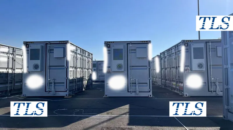
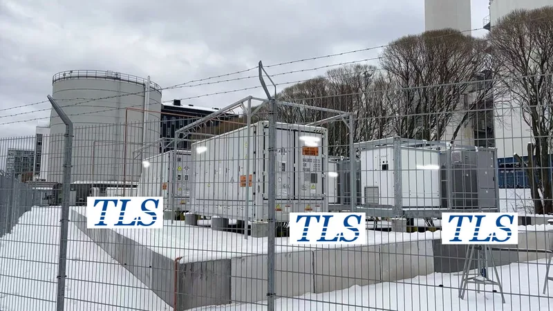
Introduction
A battery energy storage system (BESS) lives or dies by how well its direct-current (DC) side batteries and alternating-current (AC) side power-conversion system (PCS) work together. Size the DC pack too small and the PCS will throttle. Oversize it and capital cost soars. The key metric that bridges the two worlds is the DC-side C-rate (often written as 1 P, 0.5 P, 0.25 P)—the ratio between battery power (kW) and usable energy (kWh). Choosing the right C-rate for the job drives round-trip efficiency, lifetime throughput, and ultimately levelised cost of storage (LCOS). This article unpacks the math, shows how C-rate dictates AC power, and offers practical sizing rules for peak-shaving, frequency regulation, and renewable smoothing projects.
1. DC-Side C-Rate—What It Really Means
The C-rate (or P/E ratio) measures how fast a battery can be fully charged or discharged:
C-rate (P) = Battery DC Power (kW) ÷ Battery Capacity (kWh)
2. AC-Side Power—The Role of the PCS
The PCS converts DC battery energy to grid-compatible AC. It is defined by its AC-side rated power, normally expressed in kW or MW at a specific power factor.
Key facts:
3. Linking C-Rate to PCS Power
Although C-rate and PCS rating are different parameters, they must align for the target use case:
PCS rated ≈ Battery Power × ηPCS
Battery Power = C-rate × Battery Capacity
Where ηPCS is the round-trip efficiency on the AC side (typically 0.95–0.98).
5. Worked Examples
Example 1 — 0.5 P Peak-Shaving
Example 2 — 1 P Frequency Regulation
6. Common Pitfalls to Avoid
7. Optimising LCOS and Lifetime
Balancing C-rate and PCS rating is as much about economics as physics. Lower C-rates:
Conclusion
The C-rate you choose on the DC side sets the ceiling for AC-side power—and in turn defines the technical and financial performance of the entire BESS. By mapping application demands to an appropriate C-rate, translating that into battery power, and then choosing a PCS that matches within efficiency limits, engineers can hit fast-frequency-response targets, shave peaks economically, or smooth renewables without over-spending. Align the numbers, watch the efficiencies, and your storage plant will deliver maximum value throughout its life cycle.
A battery energy storage system (BESS) lives or dies by how well its direct-current (DC) side batteries and alternating-current (AC) side power-conversion system (PCS) work together. Size the DC pack too small and the PCS will throttle. Oversize it and capital cost soars. The key metric that bridges the two worlds is the DC-side C-rate (often written as 1 P, 0.5 P, 0.25 P)—the ratio between battery power (kW) and usable energy (kWh). Choosing the right C-rate for the job drives round-trip efficiency, lifetime throughput, and ultimately levelised cost of storage (LCOS). This article unpacks the math, shows how C-rate dictates AC power, and offers practical sizing rules for peak-shaving, frequency regulation, and renewable smoothing projects.
1. DC-Side C-Rate—What It Really Means
The C-rate (or P/E ratio) measures how fast a battery can be fully charged or discharged:
C-rate (P) = Battery DC Power (kW) ÷ Battery Capacity (kWh)
- 1 P (1 C): Empty to full in 1 h.
- 0.5 P: Two-hour charge/discharge.
- 0.25 P: Four-hour duration.
2. AC-Side Power—The Role of the PCS
The PCS converts DC battery energy to grid-compatible AC. It is defined by its AC-side rated power, normally expressed in kW or MW at a specific power factor.
Key facts:
- PCS power is always ≤ DC battery power because conversion losses consume 2 %–5 %.
- Efficiency varies with load, temperature, and topology (central vs. string inverters).
- Oversizing the PCS offers no benefit if the battery cannot supply the current.
3. Linking C-Rate to PCS Power
Although C-rate and PCS rating are different parameters, they must align for the target use case:
PCS rated ≈ Battery Power × ηPCS
Battery Power = C-rate × Battery Capacity
Where ηPCS is the round-trip efficiency on the AC side (typically 0.95–0.98).
- Frequency-regulation projects need bursts of full power within seconds, so the battery is sized at 1 P (it can empty in one hour) and the PCS is rated almost equal to that battery power to let the system deliver its entire capacity instantly.
- Peak-shaving or energy-arbitrage systems cycle for two-to-four hours each day; a 0.5 P battery (two-hour discharge) is enough, and the PCS is typically sized to about 50 % of the battery’s DC power, trimming inverter cost while still meeting the daily profile.
- Renewable-smoothing installations must cover gentle output ramps over four-to-six hours, so they use a low-stress 0.25 P battery, and the PCS only needs roughly 25 % of the battery’s power, because long-duration support—not peak output—is the priority.
- Pin down the duty cycle. How many cycles per day? Over what duration?
- Select the target C-rate. E.g., 0.5 P for a four-hour peak-shaving system.
- Compute power and energy.
Battery Power = C-rate × kWh
- Check economics and safety margins. Re-iterate if LCOS, temperature rise, or fault-current limits fail.
5. Worked Examples
Example 1 — 0.5 P Peak-Shaving
- Scenario: Industrial user cycles once daily over 4 h.
- Energy needed: 200 kWh usable.
- Battery power: 0.5 P × 200 kWh = 100 kW.
- PCS power: 100 kW × 0.98 ≈ 98 kW, but many designers cap at 50 kW to cut CapEx, accepting longer charge/discharge at partial output.
Example 2 — 1 P Frequency Regulation
- Scenario: Grid operator calls for ±100 kW within seconds.
- Energy window: 100 kWh (charge or discharge in 1 h).
- Battery power: 1 P × 100 kWh = 100 kW.
- PCS power: Match at 100 kW (efficiency already budgeted in control margin).
6. Common Pitfalls to Avoid
- Assuming PCS dictates C-rate. The correct flow is: application → C-rate → battery power → PCS power.
- Oversizing PCS above battery power. This wastes capital; the extra capacity sits idle.
- Ignoring seasonal variations. Ambient temperature derates both battery and PCS output—factor these in.
- Leaving no headroom. Design at 90 % of continuous rating to handle degradation and efficiency drift.
7. Optimising LCOS and Lifetime
Balancing C-rate and PCS rating is as much about economics as physics. Lower C-rates:
- Reduce peak cell stress, boosting cycle life.
- Allow cheaper PCS hardware.
- Increase container count, land footprint, and HVAC load.
- Maximise revenue in fast-response markets (frequency, ancillary services).
- Require premium cells with thicker current collectors and robust thermal management.
- Raise fire-safety engineering requirements—particularly for high-rate LFP or NMC cells.
Conclusion
The C-rate you choose on the DC side sets the ceiling for AC-side power—and in turn defines the technical and financial performance of the entire BESS. By mapping application demands to an appropriate C-rate, translating that into battery power, and then choosing a PCS that matches within efficiency limits, engineers can hit fast-frequency-response targets, shave peaks economically, or smooth renewables without over-spending. Align the numbers, watch the efficiencies, and your storage plant will deliver maximum value throughout its life cycle.