- Published on
In today's energy-driven world, the Battery Management System (BMS) plays a critical role across various sectors, from electric vehicles (EVs) and portable electronics to industrial and renewable energy storage solutions. This advanced technology acts as the "smart brain" of battery systems, managing operations to enhance performance, safety, and lifespan.
### What is a Battery Management System (BMS)?
A Battery Management System is an electronic control unit that monitors, manages, and protects battery systems. It continuously measures critical parameters like voltage, current, and temperature. By analyzing these real-time data, the BMS ensures that batteries operate efficiently, safely, and reliably, even under challenging conditions.
### Key Functions of BMS:
#### Battery State Monitoring
- **Voltage Monitoring:** Tracks the voltage of individual battery cells and the entire battery pack, identifying issues like overcharging or over-discharging.
- **Current Monitoring:** Measures the direction and magnitude of the current during charging and discharging, safeguarding batteries from harmful conditions.
- **Temperature Monitoring:** Prevents overheating by using sensors to detect temperature fluctuations, activating cooling or heating systems as needed.
#### Battery Protection
- **Overcharge Protection:** Automatically stops charging when the battery reaches its maximum capacity, preventing overheating and potential damage.
- **Over-discharge Protection:** Disconnects the load before the battery voltage drops below safe levels, preserving battery capacity and lifespan.
- **Overcurrent Protection:** Cuts off excessive current to prevent battery damage or safety hazards.
- **Thermal Protection:** Manages battery temperature by controlling cooling and heating systems, maintaining safe operating conditions.
#### Battery Balancing
Battery balancing addresses inconsistencies in cell performance, which can reduce overall battery efficiency. BMS uses two primary methods:
- **Active Balancing:** Transfers energy from higher-charged cells to lower-charged ones, promoting efficiency.
- **Passive Balancing:** Dissipates excess energy from high-voltage cells via resistors, balancing cell capacities economically.
#### Battery State Estimation
- **State of Charge (SOC):** Estimates remaining battery capacity, crucial for user convenience and efficiency.
- **State of Health (SOH):** Evaluates battery degradation and capacity reduction, guiding maintenance and replacements.
### Components of BMS
- **Hardware:** Includes microcontrollers, voltage/current sensors, temperature sensors, communication interfaces, and protective circuits.
- **Software:** Contains algorithms for data processing, SOC and SOH estimation, balancing control, and communication protocols.
### Working Principle of BMS
The BMS workflow consists of three main processes: data acquisition, analysis, and control execution. Sensors continuously collect voltage, current, and temperature data, processed and analyzed by the main controller. If abnormal conditions are detected, the BMS implements protective actions, ensuring the battery operates within safe and optimal limits.
### Future Trends in BMS Technology
Advancements in BMS technology include integrating artificial intelligence and machine learning to enhance battery state estimation accuracy, developing highly efficient balancing methods, and improving safety and reliability through redundant and intelligent designs. Additionally, BMS systems will increasingly connect to IoT platforms, enabling remote management and predictive maintenance, crucial for future smart energy ecosystems.
Battery Management Systems are integral to the sustainable and safe operation of modern battery technologies, significantly impacting performance, safety, and longevity.

- Published on
Power Conversion Systems (PCS) are critical components in energy storage, renewable energy applications, and industrial settings. Understanding the root causes of PCS damage can significantly enhance system reliability and performance.
Common PCS Damage Manifestations
PCS damage can present itself in various ways, including abnormal power output, frequent system shutdowns or startups, alarm indicators, communication disruptions, and overheating. Severe PCS failures, commonly referred to as "PCS blowouts," involve significant component damage such as visible burn marks, heavy smoke, and loud explosions.
Key Reasons for PCS Damage
**1. Power Device Failures:**
Failures of critical power devices like Insulated Gate Bipolar Transistors (IGBTs) or MOSFETs often result in PCS malfunction. Common failure modes include:
- **Latch-up Effect:** Triggered by excessive current or high temperatures causing internal short-circuits.
- **Thermal Runaway:** Resulting from inadequate cooling or overload, causing exponential temperature rise and eventual component burnout.
- **Avalanche Breakdown:** Occurs during sudden voltage spikes beyond device tolerance, typical in inductive load environments.
- **Wire Bond Lift-off:** Fatigue failures from repeated thermal cycling lead to increased resistance and overheating.
**2. Capacitor Failures:**
Capacitor issues frequently arise due to:
- **Electrolyte Drying:** High operating temperatures cause electrolyte evaporation, elevating internal resistance and heat buildup.
- **Excessive Ripple Voltage:** High-frequency ripple currents shorten capacitor life and effectiveness.
- **Voltage Imbalance:** Unequal voltage distribution across series-connected capacitors results in premature breakdown.
- **Partial Discharge:** Occurs in film capacitors when operating voltages exceed recommended limits, causing internal insulation failure.
**3. Magnetic Component Issues:**
Damage to inductors or transformers includes:
- **Saturation:** Excessive current leading to decreased inductance and distorted waveforms.
- **Insulation Breakdown:** High-frequency operation can cause insulation deterioration, resulting in short circuits.
**4. Control Board Faults:**
Control board issues can manifest through:
- **EMC Interference:** High-frequency switching noise causing microcontroller malfunctions and erroneous operations.
- **Software Logic Errors:** Delays in protection mechanisms, especially overcurrent protection, leading to catastrophic failures.
Severe PCS Blowout Scenarios
- **DC-side Short Circuits:** Caused by battery reversal or foreign object-induced short circuits, rapidly releasing energy stored in DC capacitors.
- **Shoot-Through Failures:** Concurrent conduction of IGBTs due to overlapping signals or faulty PCB layouts, directly short-circuiting the DC bus.
- **Grid-side Surges:** Lightning or grounding faults propagating through the PCS, causing component overvoltage and subsequent failures.
- **Cooling System Failures:** Water cooling leaks leading to internal short circuits.
Preventive Measures and Reliability Enhancement
To prevent PCS damage, adopting comprehensive design and testing practices is essential:
- **Advanced Thermal Management:** Use thermal simulations to optimize transient and steady-state cooling solutions.
- **Robust Electrical Insulation:** Adhere to international standards (IEC 61800-5-1) for creepage and clearance distances.
- **Multilevel Protection Logic:** Implement hardware-based fast-response protections supplemented by FPGA and MCU-based monitoring systems.
- **Rigorous Component Testing:** Conduct accelerated lifecycle tests (ALT and HALT) to identify weaknesses early.
By understanding and addressing these PCS damage mechanisms, engineers can greatly enhance system durability and operational reliability, safeguarding investments in renewable energy and industrial applications.
- Published on
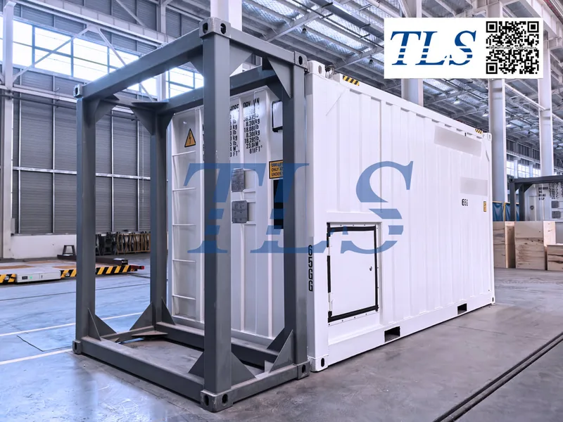
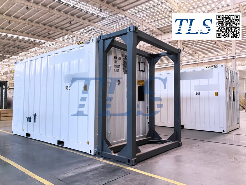
In hazardous environments, extreme climates, or industrial settings with stringent air quality requirements, specialized containers must maintain a positive pressure environment to ensure personnel safety, stable equipment operation, and prevent the ingress of external pollutants. This article delves into the types of specialized containers that require positive pressure environments, their importance, and their applications.
What is a Positive Pressure Environment?
A positive pressure environment refers to a condition where the internal pressure of a container is higher than the external ambient pressure. This is achieved through continuous air supply , which prevent harmful gases, dust, or moisture from entering the container.pressurized systems typically include pressure control systems, gas monitors, and explosion-proof certifications (such as ATEX, IECEx, CNEX) to meet industrial and safety standards.
Specialized Containers Requiring Positive Pressure Environments and Their Applications
1. Explosion-proof Positive Pressure Container
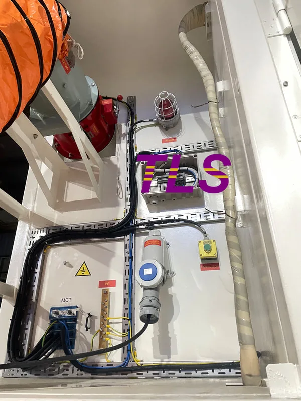
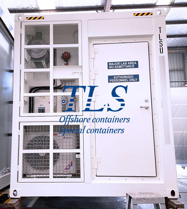
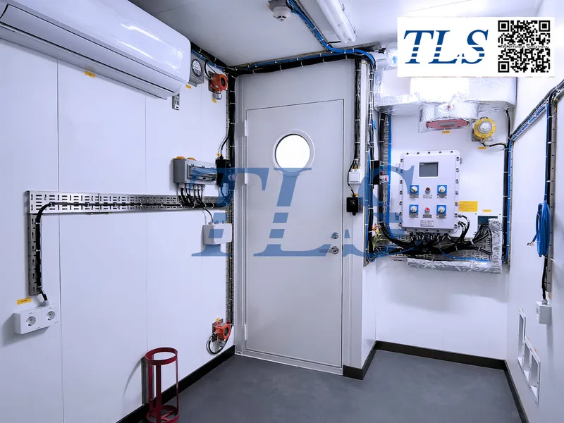
Explosion-proof positive pressure containers are used in oil and gas drilling platforms (Zone 1 & Zone 2), chemical plants, refineries, LNG stations, and other industrial sites with flammable or explosive gases. The positive pressure environment prevents the entry of combustible and toxic gases such as methane (CH₄) and hydrogen sulfide (H₂S), reducing the risk of explosions and poisoning. Additionally, it ensures compliance with explosion-proof certification standards, enabling safe operation of equipment and personnel in hazardous environments.
2. Motor Control Center Room (MCC Shelter)
MCC shelters are widely used in oil and gas drilling platforms, chemical plants, mining operations, power plants, and offshore wind farms. The positive pressure environment prevents the ingress of flammable gases, reducing the risk of fire or explosion caused by electrical equipment. It also protects control devices such as PLCs, frequency converters, and switchboards from damage caused by moisture, and corrosive gases, while safeguarding personnel health by preventing exposure to toxic gases.
3. MWD/LWD Cabin (Measurement While Drilling/Logging While Drilling Cabin)
MWD/LWD cabins are primarily used in oil and gas drilling operations, both onshore and offshore, for measurement and logging while drilling. The positive pressure environment prevents harmful gases such as hydrogen sulfide (H₂S) and methane from entering the cabin during drilling, ensuring operational safety. It also maintains a clean and dry air environment for electronic measurement devices, computers, and remote monitoring systems, ensuring their stable operation.
4. MUD Logging Cabin
MUD logging cabins are used in oil and gas logging operations, formation monitoring, and drilling data analysis. The positive pressure environment prevents combustible gases released by drilling mud from entering the cabin, reducing the risk of explosions or poisoning. It also maintains constant air pressure and clean air, improving the accuracy of instrument analysis and protecting the health of operators.
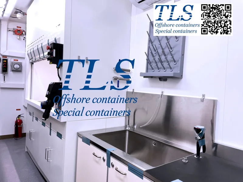
5. Lab Container
Lab containers are used in petrochemical laboratories, gas analysis, environmental monitoring, and laboratories on offshore drilling platforms and refineries. The positive pressure environment prevents external pollutants or harmful gases from affecting experimental results and protects high-precision instruments from damage caused by moisture, and corrosive gases.
6. Application of Positive Pressure in Accommodation Modules
If accommodation modules are located on offshore drilling platforms, hazardous chemical plants, or extreme environments (such as polar regions, deserts, or high-humidity areas), they also require positive pressure systems. The positive pressure environment prevents the intrusion of toxic or harmful gases, ensuring the safety of occupants, while providing a constant supply of fresh air to maintain a comfortable living environment.
Conclusion
The application of positive pressure environments in specialized containers is an indispensable safety measure in modern industrial and energy sectors. Whether it is explosion-proof positive pressure containers, MCC shelters, MWD/LWD cabins, MUD logging cabins, lab containers, or accommodation modules, positive pressure systems play a critical role. They not only prevent the intrusion of harmful gases and pollutants but also ensure the safety of equipment and personnel, providing a stable and efficient working environment. In hazardous environments and extreme climates, Pressurized Containers have become a key technological solution for ensuring industrial production and personnel safety.
TLS Offshore Containers / TLS Special Containers is a global supplier of standard and customised containerised solutions.
Wherever you are in the world TLS can help you, please contact us.
Product brochures:
Offshore pressurised mud logging cabin brochure
MCC | Switchgear | VFD | VSD pressurised shelter
Keywords:#Positive Pressure Environment, #Specialized Containers, #Hazardous Environments, #Air Filtration Systems, #Explosion-proof Certification,#Methane (CH₄),#Hydrogen Sulfide (H₂S),#Motor Control Center (MCC), #Measurement While Drilling (MWD), #Logging While Drilling (LWD), #MUD Logging Cabin, #Lab & Analyzer Container, #Accommodation Modules, #Industrial Safety, #Environmental Control
What is a Positive Pressure Environment?
A positive pressure environment refers to a condition where the internal pressure of a container is higher than the external ambient pressure. This is achieved through continuous air supply , which prevent harmful gases, dust, or moisture from entering the container.pressurized systems typically include pressure control systems, gas monitors, and explosion-proof certifications (such as ATEX, IECEx, CNEX) to meet industrial and safety standards.
Specialized Containers Requiring Positive Pressure Environments and Their Applications
1. Explosion-proof Positive Pressure Container
Explosion-proof positive pressure containers are used in oil and gas drilling platforms (Zone 1 & Zone 2), chemical plants, refineries, LNG stations, and other industrial sites with flammable or explosive gases. The positive pressure environment prevents the entry of combustible and toxic gases such as methane (CH₄) and hydrogen sulfide (H₂S), reducing the risk of explosions and poisoning. Additionally, it ensures compliance with explosion-proof certification standards, enabling safe operation of equipment and personnel in hazardous environments.
2. Motor Control Center Room (MCC Shelter)
MCC shelters are widely used in oil and gas drilling platforms, chemical plants, mining operations, power plants, and offshore wind farms. The positive pressure environment prevents the ingress of flammable gases, reducing the risk of fire or explosion caused by electrical equipment. It also protects control devices such as PLCs, frequency converters, and switchboards from damage caused by moisture, and corrosive gases, while safeguarding personnel health by preventing exposure to toxic gases.
3. MWD/LWD Cabin (Measurement While Drilling/Logging While Drilling Cabin)
MWD/LWD cabins are primarily used in oil and gas drilling operations, both onshore and offshore, for measurement and logging while drilling. The positive pressure environment prevents harmful gases such as hydrogen sulfide (H₂S) and methane from entering the cabin during drilling, ensuring operational safety. It also maintains a clean and dry air environment for electronic measurement devices, computers, and remote monitoring systems, ensuring their stable operation.
4. MUD Logging Cabin
MUD logging cabins are used in oil and gas logging operations, formation monitoring, and drilling data analysis. The positive pressure environment prevents combustible gases released by drilling mud from entering the cabin, reducing the risk of explosions or poisoning. It also maintains constant air pressure and clean air, improving the accuracy of instrument analysis and protecting the health of operators.
5. Lab Container
Lab containers are used in petrochemical laboratories, gas analysis, environmental monitoring, and laboratories on offshore drilling platforms and refineries. The positive pressure environment prevents external pollutants or harmful gases from affecting experimental results and protects high-precision instruments from damage caused by moisture, and corrosive gases.
6. Application of Positive Pressure in Accommodation Modules
If accommodation modules are located on offshore drilling platforms, hazardous chemical plants, or extreme environments (such as polar regions, deserts, or high-humidity areas), they also require positive pressure systems. The positive pressure environment prevents the intrusion of toxic or harmful gases, ensuring the safety of occupants, while providing a constant supply of fresh air to maintain a comfortable living environment.
Conclusion
The application of positive pressure environments in specialized containers is an indispensable safety measure in modern industrial and energy sectors. Whether it is explosion-proof positive pressure containers, MCC shelters, MWD/LWD cabins, MUD logging cabins, lab containers, or accommodation modules, positive pressure systems play a critical role. They not only prevent the intrusion of harmful gases and pollutants but also ensure the safety of equipment and personnel, providing a stable and efficient working environment. In hazardous environments and extreme climates, Pressurized Containers have become a key technological solution for ensuring industrial production and personnel safety.
TLS Offshore Containers / TLS Special Containers is a global supplier of standard and customised containerised solutions.
Wherever you are in the world TLS can help you, please contact us.
Product brochures:
Offshore pressurised mud logging cabin brochure
MCC | Switchgear | VFD | VSD pressurised shelter
Keywords:#Positive Pressure Environment, #Specialized Containers, #Hazardous Environments, #Air Filtration Systems, #Explosion-proof Certification,#Methane (CH₄),#Hydrogen Sulfide (H₂S),#Motor Control Center (MCC), #Measurement While Drilling (MWD), #Logging While Drilling (LWD), #MUD Logging Cabin, #Lab & Analyzer Container, #Accommodation Modules, #Industrial Safety, #Environmental Control
Written by Snowy
- Published on
In high-risk industries such as oil, gas, and chemicals, explosion-proof containers have become essential for ensuring operational safety. Particularly in hazardous gas environments (Zone 1 and Zone 2), these containers must not only meet basic structural strength requirements but also comply with strict explosion-proof electrical standards, ventilation regulations, and international safety certifications.
1. Key Features of Explosion-Proof Containers
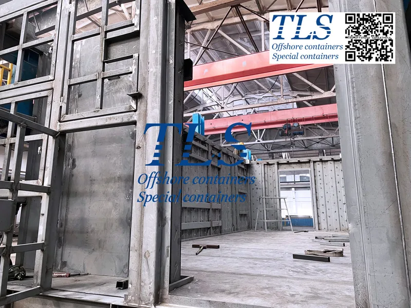
1.1 Explosion-Proof Structural Design
Each Container is constructed with high-strength weather-resistant steel to ensure airtightness and prevent flammable gas penetration.Reinforced with thickened steel plates and strengthened frames to withstand explosion impacts.
1.2 Explosion-Proof Electrical System
The electrical components must comply with IECEx, ATEX, and GB 3836 standards, including explosion-proof lighting, switches, and air conditioners.Uses explosion-proof cables and sealed junction boxes to prevent arcs or sparks from igniting flammable gases.
1.3 Ventilation & Gas Detection
Each Container is equipped with explosion-proof ventilation fans to maintain airflow and prevent gas accumulation. ntegrated explosion-proof gas detectors to monitor hazardous gases such as hydrogen (H₂) and hydrogen sulfide (H₂S) in real time.
1.4 Fire Resistance & Insulation
Built with high-performance fireproof materials, such as fire-resistant rock wool, to enhance fire resistance.Complies with EN 13501 and UL 1709 international fire safety standards, ensuring structural integrity under high temperatures.
1.5 Corrosion & Weather Resistance
Adopts C5 corrosion-resistant coatings, improving resistance to salt spray, acids, and harsh chemicals.Suitable for extreme environments such as offshore drilling platforms and chemical plants.
2. Technical Requirements for Explosion-Proof Containers
2.1 Hazardous Area Classification (Zone 1 & Zone 2)
Complies with IEC 60079 and ATEX directives, making it suitable for explosive gas environments.
2.2 Explosion-Proof Markings
All explosion-proof equipment must have clear certification markings, such as:
1)ATEX: Ex db IIB T4 Gb;
2)IECEx: Ex de IIC T5 Gb;
3)GB 3836 (China): Ex d IIB T4 Gb.
2.3 Electrical & Ventilation Systems
1) Explosion-proof power distribution system in compliance with IEC 60079-14;
2) Built-in ventilation and air exchange system to rapidly remove hazardous gases and reduce explosion risks;
3) Explosion-proof gas sensors following IEC 60079-29-2, with properly configured alarm thresholds.
2.4 Fire Resistance & Corrosion Standards
1) EN 13501-2: Fire-resistant walls with a 60-120 minute rating;UL 1709: Protection against fire for 30-60 minutes;A60: Offshore modular fire protection for 60 minutes;
2) ISO 1496: Standard for container structural strength;
3) C5 corrosion protection: Suitable for offshore and extreme industrial environments, ensuring a service life of over 15 years.
3. International Explosion-Proof Standards & Certifications
1) IECEx (International): Ensures compliance with IEC 60079 standards.
2) ATEX (European Union): Certification for equipment and protective systems in explosive environments.
3) UL (United States): UL 1709 fire resistance testing for industrial equipment.
4) CSA (Canada): Explosion-proof certification for electrical equipment.
5) CNEX/NEPSI (China): GB 3836 explosion-proof electrical equipment standards, equivalent to IEC 60079.
4. How to Choose a Qualified Explosion-Proof Container?
1) Identify the applicable hazardous area (Zone 1 or Zone 2) and match the appropriate explosion-proof rating.
2) Ensure compliance with ATEX, IECEx, and GB 3836 standards for electrical systems.
3) Verify that ventilation, gas detection, fire resistance, and corrosion protection meet industry regulations.
4) Choose suppliers with IECEx, ATEX, and UL certifications to guarantee international standard compliance.
Explosion-proof containers play a crucial role in protecting personnel and equipment in high-risk environments. When purchasing, it is essential to carefully evaluate standards and certifications to ensure long-term safety and reliability.
TLS Offshore Containers / TLS Special Containers deliver cost-effective and efficient global containerized solutions, tailored to meet the highest standards of excellence.
Wherever you are in the world TLS can help you, please contact us.
Keywords:#Explosion-proof container,#Hazardous environment,#Explosion-proof design,#ATEX certification,#IECEx standard,#GB 3836 compliance,#Zone 1 & Zone 2,#Explosion-proof electrical system,#Fire-resistant materials,#UL 1709 fire protection,#Ventilation system,#Gas detection sensors,#Corrosion resistance,#C5 anti-corrosion coating,#Industrial safety,#Offshore drilling platform,#Chemical plant safety,#Explosion-proof markings,#Structural integrity,#Safety certification
1. Key Features of Explosion-Proof Containers
1.1 Explosion-Proof Structural Design
Each Container is constructed with high-strength weather-resistant steel to ensure airtightness and prevent flammable gas penetration.Reinforced with thickened steel plates and strengthened frames to withstand explosion impacts.
1.2 Explosion-Proof Electrical System
The electrical components must comply with IECEx, ATEX, and GB 3836 standards, including explosion-proof lighting, switches, and air conditioners.Uses explosion-proof cables and sealed junction boxes to prevent arcs or sparks from igniting flammable gases.
1.3 Ventilation & Gas Detection
Each Container is equipped with explosion-proof ventilation fans to maintain airflow and prevent gas accumulation. ntegrated explosion-proof gas detectors to monitor hazardous gases such as hydrogen (H₂) and hydrogen sulfide (H₂S) in real time.
1.4 Fire Resistance & Insulation
Built with high-performance fireproof materials, such as fire-resistant rock wool, to enhance fire resistance.Complies with EN 13501 and UL 1709 international fire safety standards, ensuring structural integrity under high temperatures.
1.5 Corrosion & Weather Resistance
Adopts C5 corrosion-resistant coatings, improving resistance to salt spray, acids, and harsh chemicals.Suitable for extreme environments such as offshore drilling platforms and chemical plants.
2. Technical Requirements for Explosion-Proof Containers
2.1 Hazardous Area Classification (Zone 1 & Zone 2)
Complies with IEC 60079 and ATEX directives, making it suitable for explosive gas environments.
2.2 Explosion-Proof Markings
All explosion-proof equipment must have clear certification markings, such as:
1)ATEX: Ex db IIB T4 Gb;
2)IECEx: Ex de IIC T5 Gb;
3)GB 3836 (China): Ex d IIB T4 Gb.
2.3 Electrical & Ventilation Systems
1) Explosion-proof power distribution system in compliance with IEC 60079-14;
2) Built-in ventilation and air exchange system to rapidly remove hazardous gases and reduce explosion risks;
3) Explosion-proof gas sensors following IEC 60079-29-2, with properly configured alarm thresholds.
2.4 Fire Resistance & Corrosion Standards
1) EN 13501-2: Fire-resistant walls with a 60-120 minute rating;UL 1709: Protection against fire for 30-60 minutes;A60: Offshore modular fire protection for 60 minutes;
2) ISO 1496: Standard for container structural strength;
3) C5 corrosion protection: Suitable for offshore and extreme industrial environments, ensuring a service life of over 15 years.
3. International Explosion-Proof Standards & Certifications
1) IECEx (International): Ensures compliance with IEC 60079 standards.
2) ATEX (European Union): Certification for equipment and protective systems in explosive environments.
3) UL (United States): UL 1709 fire resistance testing for industrial equipment.
4) CSA (Canada): Explosion-proof certification for electrical equipment.
5) CNEX/NEPSI (China): GB 3836 explosion-proof electrical equipment standards, equivalent to IEC 60079.
4. How to Choose a Qualified Explosion-Proof Container?
1) Identify the applicable hazardous area (Zone 1 or Zone 2) and match the appropriate explosion-proof rating.
2) Ensure compliance with ATEX, IECEx, and GB 3836 standards for electrical systems.
3) Verify that ventilation, gas detection, fire resistance, and corrosion protection meet industry regulations.
4) Choose suppliers with IECEx, ATEX, and UL certifications to guarantee international standard compliance.
Explosion-proof containers play a crucial role in protecting personnel and equipment in high-risk environments. When purchasing, it is essential to carefully evaluate standards and certifications to ensure long-term safety and reliability.
TLS Offshore Containers / TLS Special Containers deliver cost-effective and efficient global containerized solutions, tailored to meet the highest standards of excellence.
Wherever you are in the world TLS can help you, please contact us.
Keywords:#Explosion-proof container,#Hazardous environment,#Explosion-proof design,#ATEX certification,#IECEx standard,#GB 3836 compliance,#Zone 1 & Zone 2,#Explosion-proof electrical system,#Fire-resistant materials,#UL 1709 fire protection,#Ventilation system,#Gas detection sensors,#Corrosion resistance,#C5 anti-corrosion coating,#Industrial safety,#Offshore drilling platform,#Chemical plant safety,#Explosion-proof markings,#Structural integrity,#Safety certification
Written by Snowy
- Published on
Offshore accommodation containers are essential for providing safe and efficient living spaces for crew members working in remote offshore locations. As a leading supplier of DNV 2.7-1 certified offshore accommodation containers, TLS Offshore Containers International delivers customized solutions to meet global offshore industry needs.
Advantages of TLS Offshore Accommodation Containers
1. Safety and Quality Assurance
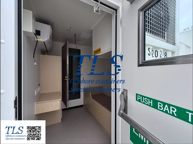
TLS accommodation containers comply with DNV 2.7-1 standards, ensuring top-tier safety and reliability for offshore operations. They are built with A60 fire-rated insulation materials and self-closing A60 doors to enhance fire protection.Equipped with escape doors and independent ventilation systems, suitable for ZONE 1 and ZONE 2 environments.C5 marine-grade coating provides superior corrosion resistance, making it ideal for extreme temperatures from -20°C to 55°C, particularly in high-temperature and sandy environments like the Middle East.
2. Modular Design for Easy Transport
Our accommodation containers feature ISO standard corner castings, allowing seamless transport by sea, land, or air. They can be used as single units or combined to form larger living spaces.Flexible space configurations with customizable furniture and equipment options.
3. Comfortable Living Environment
TLS offshore accommodation containers provide a well-insulated and climate-controlled space for optimal comfort.Rock wool insulated walls ensure excellent thermal and soundproofing properties.HVAC air conditioning system maintains a comfortable indoor temperature.Optimized electrical system for user-friendly operation.
Each 20ft offshore accommodation container is equipped with:
1) Two single beds with wardrobes and ample storage space.
2) A functional workspace, including a desk, office chair, lighting, and power outlets.
3) TV mount and internet connection for entertainment and communication.
4) Integrated bathroom facilities with a toilet, sink, shower, mirror, water heater, ventilation, and heating system for a self-sufficient living experience.
Innovative Design for Global Offshore Environments
Offshore environments are dynamic and challenging. TLS accommodation containers are designed to withstand extreme conditions, offering:
1. Efficient air conditioning and ventilation systems, ensuring comfort in high-temperature and high-humidity climates, especially in the Middle East.
2. Adopts a dust-proof sealing structure to effectively reduce dust infiltration while ensuring ventilation for a habitable environment.
3. Energy-saving lighting system, reducing power consumption and supporting sustainability initiatives.
4. Customizable design, compliant with local safety and operational regulations for seamless integration into global offshore projects.
Why Choose TLS Offshore Accommodation Containers?
At TLS Offshore Containers International, we prioritize quality, durability, and customization to ensure our offshore accommodation solutions meet the highest safety and comfort standards.
Designed for extreme environments, our containers enhance operational efficiency with flexible design and outstanding performance. Whether facing extreme temperatures, high humidity, or frequent sandstorms, TLS offshore accommodation containers provide a reliable and long-lasting solution.
TLS Offshore Containers / TLS Special Containers is a global supplier of standard and customised containerised solutions.
Wherever you are in the world TLS can help you, please contact us.
Please download TLS accommodation modular brochure , TLS ABS approved offshore accommodation module brochure for reference.
Keywords:#Offshore Accommodation, #TLS Offshore Containers, #DNV 2.7-1 Certified , #Safety Standards, #Fire-Rated Insulation, #Modular Design, #ISO Standard, #Climate-Controlled, #Thermal Insulation, #Soundproofing,#HVAC System,#Corrosion Resistance,#C5 Marine Coating,#Extreme Temperature Resistance,#Customizable Design ,# Energy-Efficient Lighting,#Integrated Bathroom,#Remote Offshore Locations,#High Humidity Resistance ,#Sandstorm Protection
Advantages of TLS Offshore Accommodation Containers
1. Safety and Quality Assurance
TLS accommodation containers comply with DNV 2.7-1 standards, ensuring top-tier safety and reliability for offshore operations. They are built with A60 fire-rated insulation materials and self-closing A60 doors to enhance fire protection.Equipped with escape doors and independent ventilation systems, suitable for ZONE 1 and ZONE 2 environments.C5 marine-grade coating provides superior corrosion resistance, making it ideal for extreme temperatures from -20°C to 55°C, particularly in high-temperature and sandy environments like the Middle East.
2. Modular Design for Easy Transport
Our accommodation containers feature ISO standard corner castings, allowing seamless transport by sea, land, or air. They can be used as single units or combined to form larger living spaces.Flexible space configurations with customizable furniture and equipment options.
3. Comfortable Living Environment
TLS offshore accommodation containers provide a well-insulated and climate-controlled space for optimal comfort.Rock wool insulated walls ensure excellent thermal and soundproofing properties.HVAC air conditioning system maintains a comfortable indoor temperature.Optimized electrical system for user-friendly operation.
Each 20ft offshore accommodation container is equipped with:
1) Two single beds with wardrobes and ample storage space.
2) A functional workspace, including a desk, office chair, lighting, and power outlets.
3) TV mount and internet connection for entertainment and communication.
4) Integrated bathroom facilities with a toilet, sink, shower, mirror, water heater, ventilation, and heating system for a self-sufficient living experience.
Innovative Design for Global Offshore Environments
Offshore environments are dynamic and challenging. TLS accommodation containers are designed to withstand extreme conditions, offering:
1. Efficient air conditioning and ventilation systems, ensuring comfort in high-temperature and high-humidity climates, especially in the Middle East.
2. Adopts a dust-proof sealing structure to effectively reduce dust infiltration while ensuring ventilation for a habitable environment.
3. Energy-saving lighting system, reducing power consumption and supporting sustainability initiatives.
4. Customizable design, compliant with local safety and operational regulations for seamless integration into global offshore projects.
Why Choose TLS Offshore Accommodation Containers?
At TLS Offshore Containers International, we prioritize quality, durability, and customization to ensure our offshore accommodation solutions meet the highest safety and comfort standards.
Designed for extreme environments, our containers enhance operational efficiency with flexible design and outstanding performance. Whether facing extreme temperatures, high humidity, or frequent sandstorms, TLS offshore accommodation containers provide a reliable and long-lasting solution.
TLS Offshore Containers / TLS Special Containers is a global supplier of standard and customised containerised solutions.
Wherever you are in the world TLS can help you, please contact us.
Please download TLS accommodation modular brochure , TLS ABS approved offshore accommodation module brochure for reference.
Keywords:#Offshore Accommodation, #TLS Offshore Containers, #DNV 2.7-1 Certified , #Safety Standards, #Fire-Rated Insulation, #Modular Design, #ISO Standard, #Climate-Controlled, #Thermal Insulation, #Soundproofing,#HVAC System,#Corrosion Resistance,#C5 Marine Coating,#Extreme Temperature Resistance,#Customizable Design ,# Energy-Efficient Lighting,#Integrated Bathroom,#Remote Offshore Locations,#High Humidity Resistance ,#Sandstorm Protection
Written by Snowy
- Published on
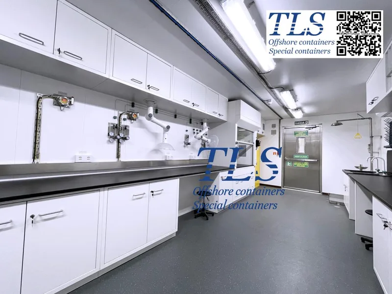
In today’s fast-paced scientific landscape, the demand for innovative, mobile, and secure laboratory solutions is higher than ever. Researchers require safe environments to conduct experiments, analyze samples, and handle hazardous materials without compromising safety. 20' offshore negative pressure lab containers are transforming laboratory research by offering a controlled, portable, and compliant workspace for various industries.
What Are Offshore Negative Pressure Lab Containers?
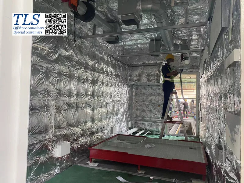
Offshore negative pressure lab containers are self-contained laboratory units engineered to maintain negative air pressure inside the workspace. This design ensures that hazardous substances, contaminants, and pathogens remain contained within the lab, preventing their release into the external environment. These specialized labs are ideal for offshore applications, remote research sites, and emergency response teams.
Key Features of 20' Offshore Negative Pressure Lab Containers
Designed to meet the highest industry standards, these compact 20-foot containers offer state-of-the-art safety and functionality. Key features include:
Applications Across Multiple Industries
The versatility and safety of offshore negative pressure lab containers make them an invaluable asset in various scientific and industrial fields:
1. Biotechnology & Pharmaceutical Research
Why Choose a 20' Offshore Negative Pressure Lab Container?
Investing in a TLS Offshore Lab Container ensures:
Conclusion
As research and industrial needs evolve, 20' offshore negative pressure lab containers provide a secure, mobile, and efficient solution for handling sensitive experiments and hazardous materials. With their advanced safety features, adaptability, and compliance with industry regulations, these lab containers are revolutionizing the way scientific research is conducted offshore and in remote locations.
Looking for a high-performance negative pressure lab container? Contact TLS Offshore Containers today to explore how our state-of-the-art lab solutions can support your research needs!
TLS Offshore Containers / TLS Special Containers is a global supplier of standard and customised containerised solutions.
Wherever you are in the world TLS can help you, please contact us.
Please download Laboratory container brochure for reference.
Keywords: #Offshore negative pressure lab container, #20' negative pressure lab container, #Portable offshore lab solutions, #Mobile laboratory container, #Hazardous material containment lab, #Offshore laboratory research, #Negative pressure lab for hazardous materials, #Mobile containment lab, #Offshore research container solutions
What Are Offshore Negative Pressure Lab Containers?
Offshore negative pressure lab containers are self-contained laboratory units engineered to maintain negative air pressure inside the workspace. This design ensures that hazardous substances, contaminants, and pathogens remain contained within the lab, preventing their release into the external environment. These specialized labs are ideal for offshore applications, remote research sites, and emergency response teams.
Key Features of 20' Offshore Negative Pressure Lab Containers
Designed to meet the highest industry standards, these compact 20-foot containers offer state-of-the-art safety and functionality. Key features include:
- Negative Pressure System: Ensures air pressure inside the container is lower than outside, preventing hazardous material from escaping.
- Advanced Filtration Technology: HEPA and activated carbon filters remove airborne contaminants, ensuring a clean and safe workspace.
- Modular and Customizable Design: Configurable interiors allow for the integration of specialized laboratory equipment based on specific research needs.
- Robust Offshore-Grade Construction: Made from high-quality, corrosion-resistant materials, these containers withstand harsh offshore conditions.
- Compliance with Safety Standards: Designed to adhere to industry regulations, ensuring safe operations in sensitive environments.
Applications Across Multiple Industries
The versatility and safety of offshore negative pressure lab containers make them an invaluable asset in various scientific and industrial fields:
1. Biotechnology & Pharmaceutical Research
- Ideal for handling biohazardous materials in vaccine development, genetic research, and drug testing.
- Provides a secure environment for pathogen studies and biopharmaceutical innovation.
- Supports air quality monitoring, pollution detection, and ecological analysis in remote locations.
- Enables real-time data collection in offshore and marine research projects.
- Enhances safety for chemical analysis and testing in offshore facilities.
- Protects personnel by minimizing exposure to toxic or volatile substances.
- Enables the safe handling of infectious disease samples and medical diagnostics in offshore and remote areas.
- Ensures biosecurity compliance for handling blood samples, viruses, and other hazardous materials.
- Can be rapidly deployed in response to epidemics, pandemics, or environmental disasters.
- Serves as a mobile containment lab for emergency testing and medical evaluations.
Why Choose a 20' Offshore Negative Pressure Lab Container?
Investing in a TLS Offshore Lab Container ensures:
- Enhanced Safety – Negative pressure technology and HEPA filtration reduce contamination risks.
- Mobility & Flexibility – Easily transportable to offshore locations, ensuring on-site research capability.
- Cost-Effective Solution – Eliminates the need for constructing permanent lab facilities, making it a scalable and economical option.
- Regulatory Compliance – Meets stringent industry and safety standards for hazardous material handling.
Conclusion
As research and industrial needs evolve, 20' offshore negative pressure lab containers provide a secure, mobile, and efficient solution for handling sensitive experiments and hazardous materials. With their advanced safety features, adaptability, and compliance with industry regulations, these lab containers are revolutionizing the way scientific research is conducted offshore and in remote locations.
Looking for a high-performance negative pressure lab container? Contact TLS Offshore Containers today to explore how our state-of-the-art lab solutions can support your research needs!
TLS Offshore Containers / TLS Special Containers is a global supplier of standard and customised containerised solutions.
Wherever you are in the world TLS can help you, please contact us.
Please download Laboratory container brochure for reference.
Keywords: #Offshore negative pressure lab container, #20' negative pressure lab container, #Portable offshore lab solutions, #Mobile laboratory container, #Hazardous material containment lab, #Offshore laboratory research, #Negative pressure lab for hazardous materials, #Mobile containment lab, #Offshore research container solutions
Written by Oliver
- Published on
Unmatched Protection for Hazardous Offshore Environments
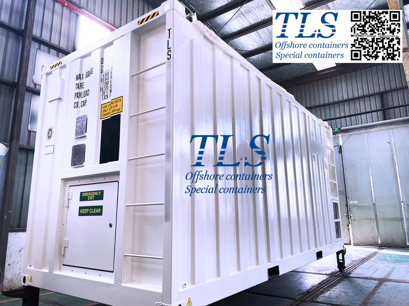
In offshore oil and gas operations, safety is paramount. The presence of flammable gases and harsh environmental conditions demands cutting-edge solutions to protect personnel and equipment. TLS introduces the Offshore Ex-Proof Positive Pressure Container, engineered to thrive in Zone 1&2 hazardous areas while ensuring compliance with ATEX&IECEx certified electrical equipment. Designed to withstand extreme offshore conditions, these containers set a new benchmark for safety, reliability, and efficiency.
What Are Offshore Ex-Proof Positive Pressure Containers?
TLS’s Offshore Explosion-Proof Positive Pressure Containers are designed specifically for hazardous offshore environments, where the risk of explosions and exposure to toxic substances is high. By maintaining a positive internal pressure, these containers prevent flammable gases from entering, thereby minimizing the risk of ignition. They provide a safe, controlled workspace for offshore operations, ensuring uninterrupted functionality in challenging conditions.
Key Benefits of TLS Offshore Ex-Proof Positive Pressure Containers
1. Maximum Safety & Explosion Protection
Why Choose TLS for Offshore Safety Solutions?
TLS is a trusted leader in the offshore container industry, specializing in explosion-proof solutions for hazardous environments. Our expert engineering team ensures that each container meets the highest safety, durability, and performance standards. Whether for offshore oil rigs, floating production units (FPSO), or drilling platforms, TLS provides tailored, state-of-the-art solutions to enhance operational safety and efficiency.
Secure Your Offshore Operations with TLS Ex-Proof ContainersInvesting in TLS Offshore Ex-Proof Positive Pressure Containers means safeguarding your personnel, equipment, and overall operations. Don't compromise on safety—contact TLS today to learn more about our custom offshore container solutions and elevate your offshore operations to the highest safety standards.
TLS Offshore Containers / TLS Special Containers is a global supplier of standard and customised containerised solutions.
Wherever you are in the world TLS can help you, please contact us.
Product brochures:
Offshore pressurised mud logging cabin brochure
MCC | Switchgear | VFD | VSD pressurised shelter
Keywords: #Offshore safety solutions, #Explosion-proof containers, #Positive pressure containers, #ATEX certified offshore containers, #IECEx certified explosion-proof containers, #Zone 1 Zone 2 hazardous areas, #Offshore hazardous environment containers, #Explosion protection for offshore operations, #Safety containers for oil rigs, #Offshore drilling safety equipment, #Explosion-proof storage containers
In offshore oil and gas operations, safety is paramount. The presence of flammable gases and harsh environmental conditions demands cutting-edge solutions to protect personnel and equipment. TLS introduces the Offshore Ex-Proof Positive Pressure Container, engineered to thrive in Zone 1&2 hazardous areas while ensuring compliance with ATEX&IECEx certified electrical equipment. Designed to withstand extreme offshore conditions, these containers set a new benchmark for safety, reliability, and efficiency.
What Are Offshore Ex-Proof Positive Pressure Containers?
TLS’s Offshore Explosion-Proof Positive Pressure Containers are designed specifically for hazardous offshore environments, where the risk of explosions and exposure to toxic substances is high. By maintaining a positive internal pressure, these containers prevent flammable gases from entering, thereby minimizing the risk of ignition. They provide a safe, controlled workspace for offshore operations, ensuring uninterrupted functionality in challenging conditions.
Key Benefits of TLS Offshore Ex-Proof Positive Pressure Containers
1. Maximum Safety & Explosion Protection
- Engineered to operate in Zone 1 and Zone 2 hazardous areas.
- ATEX/IECEx-certified components ensure compliance with international safety regulations.
- Positive pressure technology prevents the ingress of hazardous gases, reducing explosion risks.
- Constructed with high-strength materials to endure harsh marine environments.
- Resistant to corrosion, extreme temperatures, and strong winds.
- Long-lasting performance with minimal maintenance requirements.
- Tailored configurations available for workspace, control rooms, labs, or storage units.
- Options for integrated HVAC, fire suppression, and gas detection systems.
- Seamless integration with existing offshore platforms and facilities.
- Reduces downtime and risk of operational disruptions.
- Minimizes maintenance costs while ensuring compliance with safety regulations.
- Improves overall productivity by providing a safe and efficient work environment.
- Fully compliant with ATEX, IECEx, and other offshore industry standards.
- Designed to meet strict regulatory requirements for offshore hazardous areas.
- Ensures peace of mind with third-party testing and certification.
Why Choose TLS for Offshore Safety Solutions?
TLS is a trusted leader in the offshore container industry, specializing in explosion-proof solutions for hazardous environments. Our expert engineering team ensures that each container meets the highest safety, durability, and performance standards. Whether for offshore oil rigs, floating production units (FPSO), or drilling platforms, TLS provides tailored, state-of-the-art solutions to enhance operational safety and efficiency.
Secure Your Offshore Operations with TLS Ex-Proof ContainersInvesting in TLS Offshore Ex-Proof Positive Pressure Containers means safeguarding your personnel, equipment, and overall operations. Don't compromise on safety—contact TLS today to learn more about our custom offshore container solutions and elevate your offshore operations to the highest safety standards.
TLS Offshore Containers / TLS Special Containers is a global supplier of standard and customised containerised solutions.
Wherever you are in the world TLS can help you, please contact us.
Product brochures:
Offshore pressurised mud logging cabin brochure
MCC | Switchgear | VFD | VSD pressurised shelter
Keywords: #Offshore safety solutions, #Explosion-proof containers, #Positive pressure containers, #ATEX certified offshore containers, #IECEx certified explosion-proof containers, #Zone 1 Zone 2 hazardous areas, #Offshore hazardous environment containers, #Explosion protection for offshore operations, #Safety containers for oil rigs, #Offshore drilling safety equipment, #Explosion-proof storage containers
Written by Oliver
- Published on
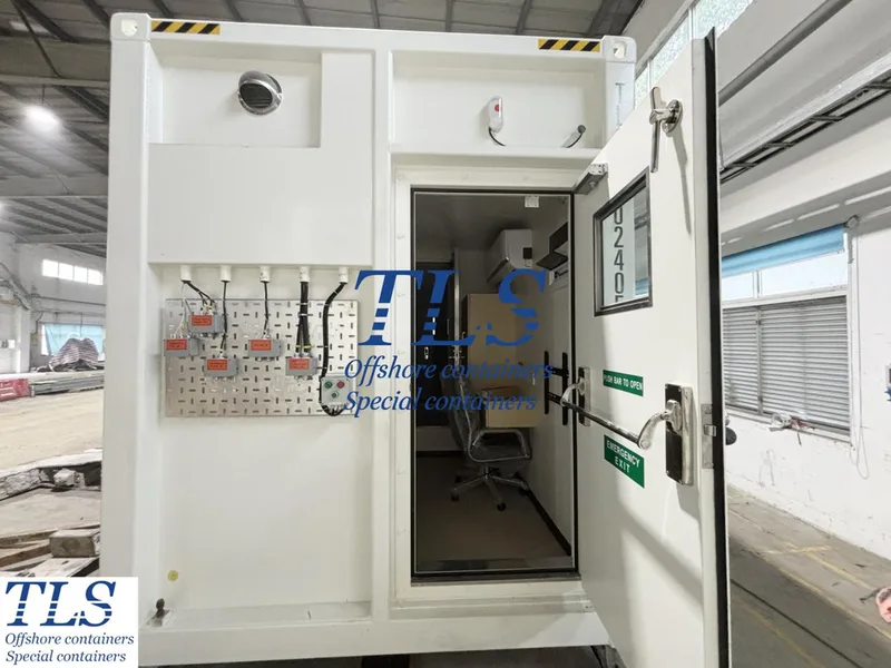
In the high-risk environments of offshore operations, safety, efficiency, and regulatory compliance are non-negotiable. Remote Operated Vehicles (ROVs) play a crucial role in underwater inspections, maintenance, and repair tasks in hazardous zones. To ensure seamless operations while prioritizing safety, ROV Ex-Proof Control Cabins and Containers have emerged as essential solutions for offshore and industrial applications.
What Are ROV Ex-Proof Control Cabins and Containers?
ROV Ex-Proof Control Cabins and Containers are specialized enclosures designed to house control systems for remotely operated vehicles in hazardous locations. These include offshore drilling platforms, oil and gas rigs, chemical processing plants, and other explosion-prone areas where standard electronic equipment could pose significant ignition risks.
Built to withstand extreme conditions, these explosion-proof cabins ensure that critical control functions remain operational even in the most challenging offshore environments.
Ensuring Compliance with Safety Standards
Working in hazardous locations requires strict adherence to global safety regulations. ROV Ex-Proof Control Cabins and Containers comply with key industry standards, including:
By meeting these stringent standards, these control cabins mitigate the risk of explosions, ensuring maximum safety for personnel and assets.
Key Features and Advantages of ROV Ex-Proof Control Cabins
1. Explosion-Proof Engineering
ROV Ex-Proof Control Cabins are constructed using explosion-proof materials and designs, preventing hazardous gases and vapors from igniting inside the enclosure.
2. Durable and Robust Construction
Built to endure harsh offshore conditions, these control cabins are resistant to extreme temperatures, high pressure, and corrosive marine environments, ensuring long-term reliability.
3. Advanced Control and Monitoring Systems
Equipped with state-of-the-art control systems, these cabins enable precise and efficient ROV operations, improving offshore performance and safety.
4. Remote Surveillance Capabilities
With real-time telemetry and monitoring features, operators can track critical parameters remotely, enhancing situational awareness and enabling rapid response to any anomalies or emergencies.
5. Modular and Portable Design
Designed for easy transportation and quick installation, these modular control cabins offer flexibility in deployment, making them suitable for various offshore and industrial applications.
Operational Benefits of ROV Ex-Proof Control Cabins
Integrating ROV Ex-Proof Control Cabins and Containers into offshore projects significantly improves operational efficiency and risk management. Key benefits include:
Conclusion: A Smart Investment for Offshore Safety
ROV Ex-Proof Control Cabins and Containers are transforming offshore operations by combining advanced technology with stringent safety compliance. Investing in these specialized control enclosures ensures reliable ROV operations, enhances efficiency, and safeguards personnel in hazardous environments.
For companies operating in offshore and industrial sectors, adopting explosion-proof control cabins is not just a regulatory necessity but a strategic advantage. By implementing these solutions, businesses can navigate hazardous environments with confidence while optimizing performance and safety.
TLS Offshore Containers / TLS Special Containers is a global supplier of standard and customised containerised solutions.
Wherever you are in the world TLS can help you, please contact us.
Product brochures:
Offshore pressurised mud logging cabin brochure
MCC | Switchgear | VFD | VSD pressurised shelter
Keywords: #Offshore explosion-proof cabins, #Hazardous environment control rooms, #Ex-proof ROV control solutions, #ATEX-certified offshore containers, #IECEx explosion-proof control cabins, #Oil and gas safety equipment, #ROV operations in hazardous areas, #Ex-proof equipment for offshore rigs, #Safe zone ROV control cabins, #Industrial explosion-proof monitoring solutions, #Hazardous area electrical enclosures
What Are ROV Ex-Proof Control Cabins and Containers?
ROV Ex-Proof Control Cabins and Containers are specialized enclosures designed to house control systems for remotely operated vehicles in hazardous locations. These include offshore drilling platforms, oil and gas rigs, chemical processing plants, and other explosion-prone areas where standard electronic equipment could pose significant ignition risks.
Built to withstand extreme conditions, these explosion-proof cabins ensure that critical control functions remain operational even in the most challenging offshore environments.
Ensuring Compliance with Safety Standards
Working in hazardous locations requires strict adherence to global safety regulations. ROV Ex-Proof Control Cabins and Containers comply with key industry standards, including:
- ATEX (Atmosphères Explosibles) Certification – Ensuring compliance with European explosion-proof requirements.
- IECEx (International Electrotechnical Commission Explosive Atmospheres) Certification – Verifying international safety for equipment in explosive environments.
- Other regional and industry-specific certifications as required.
By meeting these stringent standards, these control cabins mitigate the risk of explosions, ensuring maximum safety for personnel and assets.
Key Features and Advantages of ROV Ex-Proof Control Cabins
1. Explosion-Proof Engineering
ROV Ex-Proof Control Cabins are constructed using explosion-proof materials and designs, preventing hazardous gases and vapors from igniting inside the enclosure.
2. Durable and Robust Construction
Built to endure harsh offshore conditions, these control cabins are resistant to extreme temperatures, high pressure, and corrosive marine environments, ensuring long-term reliability.
3. Advanced Control and Monitoring Systems
Equipped with state-of-the-art control systems, these cabins enable precise and efficient ROV operations, improving offshore performance and safety.
4. Remote Surveillance Capabilities
With real-time telemetry and monitoring features, operators can track critical parameters remotely, enhancing situational awareness and enabling rapid response to any anomalies or emergencies.
5. Modular and Portable Design
Designed for easy transportation and quick installation, these modular control cabins offer flexibility in deployment, making them suitable for various offshore and industrial applications.
Operational Benefits of ROV Ex-Proof Control Cabins
Integrating ROV Ex-Proof Control Cabins and Containers into offshore projects significantly improves operational efficiency and risk management. Key benefits include:
- Reduced Downtime: Durable construction and high-performance design minimize equipment failures, ensuring maximum uptime and operational continuity.
- Enhanced Safety: Explosion-proof technology eliminates risks associated with electrical equipment in hazardous environments, prioritizing worker and asset safety.
- Streamlined Maintenance: Modular designs facilitate easy servicing, repairs, and component replacements, minimizing disruption to ongoing operations.
Conclusion: A Smart Investment for Offshore Safety
ROV Ex-Proof Control Cabins and Containers are transforming offshore operations by combining advanced technology with stringent safety compliance. Investing in these specialized control enclosures ensures reliable ROV operations, enhances efficiency, and safeguards personnel in hazardous environments.
For companies operating in offshore and industrial sectors, adopting explosion-proof control cabins is not just a regulatory necessity but a strategic advantage. By implementing these solutions, businesses can navigate hazardous environments with confidence while optimizing performance and safety.
TLS Offshore Containers / TLS Special Containers is a global supplier of standard and customised containerised solutions.
Wherever you are in the world TLS can help you, please contact us.
Product brochures:
Offshore pressurised mud logging cabin brochure
MCC | Switchgear | VFD | VSD pressurised shelter
Keywords: #Offshore explosion-proof cabins, #Hazardous environment control rooms, #Ex-proof ROV control solutions, #ATEX-certified offshore containers, #IECEx explosion-proof control cabins, #Oil and gas safety equipment, #ROV operations in hazardous areas, #Ex-proof equipment for offshore rigs, #Safe zone ROV control cabins, #Industrial explosion-proof monitoring solutions, #Hazardous area electrical enclosures
Written by Oliver
- Published on
Lithium battery SOH (State of Health) is a critical parameter that determines the performance and lifespan of a battery. It measures the degradation and remaining usability of a battery over time. Understanding SOH indicators helps in optimizing battery usage, prolonging lifespan, and ensuring safety. Here, we explore the key SOH indicators and factors affecting battery health.
Key SOH Indicators
### 1. Capacity Indicator
Capacity measures the maximum charge a battery can store and deliver, typically expressed in ampere-hours (Ah). It is one of the primary metrics for determining SOH. A new battery starts with 100% capacity, which gradually decreases with usage.
**Evaluation Method:**
- **Full Discharge Test:** The most accurate but time-consuming method, requiring complete discharge to measure output energy.
- **Model-Based Estimation:** Uses mathematical models to estimate capacity without full discharge.
**Example Data:**
- New battery SOH: 100%
- After 500 charge cycles: ~80%
- After 1000 charge cycles: ~60%
### 2. Internal Resistance Indicator
Internal resistance measures the resistance within the battery that affects efficiency and heat generation. Higher resistance leads to increased energy loss and heating.
**Evaluation Method:**
- **AC Impedance Test:** Uses an AC signal to measure impedance, distinguishing different resistance types.
- **DC Resistance Test:** Uses DC current to measure resistance; simpler but less precise.
**Example Data:**
- New battery resistance: ~0.1Ω
- After 500 charge cycles: ~0.2Ω
- After 1000 charge cycles: ~0.3Ω
### 3. Voltage Indicator
Battery voltage is influenced by charge state, temperature, and aging. Measuring open-circuit voltage (OCV) and dynamic voltage helps assess SOH.
**Evaluation Method:**
- **Open-Circuit Voltage (OCV):** Measures voltage without load, indicating chemical state.
- **Dynamic Voltage Test:** Measures under load to assess polarization effects.
**Example Data:**
- Typical lithium battery OCV: 3.0V - 4.2V
- Discharge cutoff voltage: ~2.5V
- Full charge voltage: ~4.2V
### 4. Self-Discharge Indicator
Self-discharge occurs when a battery loses charge while idle. Higher self-discharge rates indicate aging and potential defects.
**Evaluation Method:**
- **Static Test:** Measures voltage drop over time without usage.
**Example Data:**
- New battery self-discharge: ~1-2% per month
- After 500 charge cycles: ~2-3% per month
- After 1000 charge cycles: ~3-5% per month
Factors Affecting SOH
1. **Charge Cycle Count:** The more charge-discharge cycles, the faster capacity depletes.
2. **Depth of Discharge (DoD):** Deep discharges accelerate aging, while shallow cycles extend lifespan.
3. **Temperature Impact:** High temperatures increase degradation, while low temperatures affect performance.
4. **Charge/Discharge Rate:** Rapid charging generates heat, causing faster aging; slower rates are gentler on batteries.
Monitoring lithium battery SOH is essential for maintaining performance, extending lifespan, and ensuring safety. By understanding capacity, resistance, voltage, and self-discharge, users can take preventive measures to enhance battery efficiency and durability.
**Optimize battery usage today by following these best practices for monitoring and maintaining lithium battery SOH.**
- Published on
Lithium battery State of Health (SOH) is a crucial factor in determining battery performance and lifespan. Improper usage can lead to rapid degradation, reduced capacity, and shorter operational life. To maximize battery efficiency and longevity, it’s essential to follow best practices for battery care. This guide explores top strategies to maintain and extend lithium battery SOH effectively.
## **1. Avoid Deep Discharges: Use Shallow Charge Cycles**
- **Why?** Deep discharges increase stress on battery chemistry, leading to faster wear.
- **Best Practice:** Maintain the **State of Charge (SOC) between 20% and 80%** for optimal longevity.
- **Tip:** Avoid draining the battery below **20%** and do not keep it at **100%** for long durations.
## **2. Optimize Charging Habits**
- **Why?** Fast charging generates heat and increases chemical degradation.
- **Best Practice:**
- Prefer **slow or moderate charging** instead of high-speed charging.
- Unplug the battery **before it reaches 100%** (ideal charge range: **80-90%**).
- Use **original or certified chargers** to prevent overvoltage damage.
- Implement a **consistent charging schedule** to avoid erratic charging patterns.
## **3. Control Operating Temperature**
- **Why?** High temperatures accelerate degradation, while low temperatures reduce performance.
- **Best Practice:**
- Keep the battery within the **optimal temperature range of 15°C to 35°C (59°F to 95°F)**.
- Avoid exposing the battery to **direct sunlight** or extreme heat.
- Allow cold batteries to warm up **before charging** to prevent stress on the cells.
## **4. Reduce High Discharge Currents**
- **Why?** High power draws generate excess heat and accelerate battery wear.
- **Best Practice:** Limit **power-intensive activities** like gaming or heavy processing when running on battery power.
- **Tip:** Enable **battery-saving modes** to regulate energy consumption.
## **5. Minimize Idle and Standby Time**
- **Why?** Long idle periods lead to **self-discharge** and chemical degradation.
- **Best Practice:**
- Store batteries at **40-60% charge** if not in use for extended periods.
- Recharge the battery every **2-3 months** to prevent deep discharge damage.
## **6. Use a Smart Battery Management System (BMS)**
- **Why?** A **BMS** helps optimize charge cycles, prevent overcharging, and balance battery cells.
- **Best Practice:** Invest in devices equipped with **battery management software** to track performance.
## **7. Avoid Frequent Full Charge Cycles**
- **Why?** Repeated **0-100% charge cycles** accelerate battery aging.
- **Best Practice:** Charge in smaller increments, such as **30-80% or 20-90%**.
## **8. Follow Proper Storage Guidelines**
- **Why?** Incorrect storage conditions lead to capacity loss and degradation.
- **Best Practice:**
- Store batteries in a **cool, dry place** at a temperature of **15°C to 25°C (59°F to 77°F)**.
- Avoid exposing stored batteries to **high humidity**.
## **9. Balance Battery Cells (For Multi-Cell Systems)**
- **Why?** Unbalanced cells degrade unevenly, reducing overall battery lifespan.
- **Best Practice:** Perform **cell balancing** if using multi-cell battery packs.
## **10. Monitor SOH Regularly**
- Why? Regular SOH tracking detects early signs of degradation.
- Best Practice: Use battery monitoring apps or a BMS to check SOH parameters like capacity, voltage, and internal resistance.
Optimizing battery usage is essential for maintaining lithium battery SOH, improving efficiency, and extending lifespan. By following these best practices—avoiding deep discharges, managing temperature, optimizing charging habits, and monitoring SOH—users can significantly enhance battery performance and reliability. Implement these strategies today for longer-lasting and more efficient lithium battery usage!