- Published on
At TLS Offshore Containers International, the safety and reliability of our offshore functional containers are of utmost importance. These containers are designed to perform specific tasks in offshore environments, such as housing equipment, control rooms, workshops, and other essential functions. Given the demanding conditions these containers face, we conduct rigorous load testing and drop testing to ensure they can withstand harsh offshore environments.
Both tests are critical in verifying that our containers have the structural integrity to perform their intended functions while maintaining safety and reliability in extreme conditions. This thorough testing process ensures our offshore functional containers are ready to handle everything from rough seas to high-impact situations, making them indispensable for offshore operations.
Load Testing: Verifying Strength Under Maximum Load
At TLS Offshore Containers International, each of our offshore functional containers undergoes individual load testing to ensure they can handle the maximum weight capacity they are designed for. This involves lifting the container using its lifting sets and holding it at maximum load for 5 minutes. For containers with 4 lifting points, this test involves applying 2.5 times the maximum gross mass to simulate extreme load conditions.
The load testing process confirms that our offshore functional containers can safely support their full design weight, which may include heavy equipment, machinery, or other critical materials. By subjecting each container to this test, we ensure that they can handle the stresses of offshore operations without risk of structural failure.
Drop Testing: Simulating Harsh Offshore Conditions
Offshore environments are often characterized by rough seas and unpredictable conditions, where containers may experience sudden impacts. To ensure our containers can withstand these extremes, we subject each offshore functional container to drop testing.
During drop testing, the container is designed to simulate real-world conditions, including being dropped from a height of at least 50mm onto a rigid surface such as a concrete floor, potentially covered with wooden planks no thicker than 50mm. This drop gives the container a speed of at least 1 meter per second upon impact, simulating the kinds of loads and collisions containers may face during loading and unloading operations, particularly when subjected to rough sea conditions with significant wave heights of up to 6 meters.
This test is essential for ensuring that the offshore functional container can endure local impact loads—such as hitting other deck cargo or rigid ship structures—without compromising its structural integrity. It prepares the container for real-world conditions where extreme loads and high-impact scenarios are the norm.
Why Load and Drop Testing Are Essential
1. Ensuring Safety: Both load and drop testing are essential to guarantee the safety of offshore personnel and equipment housed within these functional containers. TLS Offshore Containers International’s testing ensures that containers can withstand the extreme weight and forces encountered during operations, safeguarding workers and valuable assets.
2. Durability and Longevity: The tests also confirm that our offshore functional containers are built to last in challenging environments. By validating their strength, we ensure that they remain functional over extended periods, minimizing maintenance and replacement costs.
3. Regulatory Compliance: Our testing procedures ensure that our containers meet international safety and design standards, including DNV GL and ISO. This compliance is crucial for successful offshore operations, reducing legal and operational risks.
4. Reducing Risk of Failures: Rigorous testing minimizes the likelihood of container failures during critical operations. Offshore environments are inherently risky, and ensuring the robustness of the containers reduces the potential for accidents, making operations more reliable.
5. Operational Efficiency: With load and drop testing, we guarantee that our containers are ready for immediate deployment in offshore conditions, ensuring seamless and efficient operations without the need for further testing or adjustments.
TLS Offshore Containers International: Committed to Quality
At TLS Offshore Containers International, we are committed to delivering offshore functional containers that exceed industry standards. Our comprehensive load and drop testing procedures ensure that every container we produce is robust enough to handle the extreme demands of offshore environments, providing reliable and safe solutions for housing critical functions.
By investing in stringent testing processes, TLS Offshore Containers International guarantees that our products will meet and surpass the expectations of our clients. Whether it’s ensuring that containers can endure maximum loads or withstand high-impact collisions during sea operations, our containers are designed to perform reliably and safely.
Through thorough load and drop testing, TLS Offshore Containers International ensures that every offshore functional container is ready for the challenges it will face, providing operational efficiency and safety for offshore projects worldwide.
- Published on
In today’s energy landscape, the integration of renewable energy sources and the optimization of energy storage systems are more important than ever. A key technology enabling this integration is the Energy Management System (EMS). EMS plays a vital role in hybrid power setups, where it controls and optimizes the flow of energy between various sources, including renewable energy, traditional power plants, and Battery Energy Storage Systems (BESS). By leveraging advanced EMS functionalities, operators can significantly enhance the efficiency, reliability, and sustainability of their energy systems.
The Core Functions of EMS in Hybrid Power Systems
An EMS serves as the brain of a hybrid energy system, orchestrating the interactions between different energy sources and loads. It ensures that energy is generated, stored, and utilized in the most efficient manner possible. Here’s how the EMS functions within a hybrid system:
1. Active Power Control:
The EMS manages the active power output of both photovoltaic (PV) systems and batteries. By adjusting the power output in response to grid demands, it helps stabilize the grid and ensures that the energy supply meets the load requirements. This function is crucial in preventing grid imbalances that could lead to power outages or inefficiencies.
2. Energy Shifting:
Energy shifting allows the EMS to store excess energy generated during low-demand periods and release it when demand is high. This function is particularly important in renewable energy systems, where generation can be unpredictable. By shifting energy, the EMS maximizes the use of renewable resources and reduces reliance on traditional power sources.
3. Ramp Rate Control and Power Smoothing:
To maintain grid stability, the EMS controls the rate at which power output increases or decreases. This ramp rate control, combined with power smoothing, helps mitigate the effects of rapid changes in power generation, such as those caused by sudden changes in sunlight or wind. These functions are essential for integrating renewable energy sources into the grid without causing disruptions.
4. Peak Load Shaving:
During periods of peak demand, the EMS can reduce the load on the grid by discharging stored energy from the BESS. This peak load shaving function not only alleviates stress on the grid but also helps reduce energy costs by minimizing the need for expensive peak power generation.
5. Grid Services and Synchronization:
Advanced EMS configurations provide grid services that enhance grid reliability and performance. This includes frequency and voltage control, reactive power management, and grid synchronization. These services ensure that the hybrid system can operate in harmony with the larger power grid, contributing to overall grid stability.
6. Support for Black Start and Redundancy:
In the event of a power outage, an EMS with black start capabilities can restart the system independently, providing critical support during emergencies. Additionally, redundancy features in EMS ensure that the system continues to operate even if one component fails, enhancing the overall reliability of the energy supply.
Optimizing Hybrid Systems with Advanced EMS
Advanced EMS solutions offer a wide range of functionalities that can be tailored to specific hybrid system configurations. Whether managing a simple setup with minimal energy storage or a complex system integrating multiple renewable sources and large-scale BESS, the EMS is crucial for optimizing energy flow, reducing operational costs, and improving the sustainability of the energy system.
By leveraging the full potential of an EMS, operators can not only enhance the efficiency and reliability of their hybrid energy systems but also contribute to the broader goal of sustainable energy production. As the demand for renewable energy grows, the role of EMS in managing and optimizing these systems will become increasingly important.
Conclusion
The Energy Management System is a critical component in the successful operation of hybrid power systems. From active power control to grid synchronization, the EMS ensures that energy is managed efficiently and sustainably. As energy systems continue to evolve, advanced EMS functionalities will play a key role in optimizing energy use, supporting grid stability, and integrating renewable energy sources into the global energy mix.
- Published on
Battery Energy Storage Systems (BESS) are essential in the modern energy landscape, providing a reliable solution for storing and managing energy from renewable sources. These systems store excess energy when production is high and release it when demand exceeds supply, ensuring grid stability. Three crucial components— inverters, transformers, and switchgear—are fundamental to the effective operation of BESS. Understanding the roles of these components is key to maximizing the performance and reliability of your energy storage system.
The Dual Role of the Inverter in BESS
The inverter is a critical component in BESS, serving two primary functions: converting direct current (DC) stored in batteries to alternating current (AC) for grid use and converting AC from the grid to DC to charge the batteries. This bidirectional capability makes the inverter essential for both energy storage and utilization.
When the energy needs to be stored, the inverter converts the AC from the grid or other power sources into DC, which is then stored in the batteries. Conversely, when the stored energy needs to be used, the inverter efficiently converts the DC back into AC, making it suitable for grid integration or powering AC-dependent devices.
Modern inverters also incorporate advanced grid support functionalities, such as peak shaving, energy shifting, and dynamic grid stabilization. These features ensure that the BESS operates efficiently and reliably, even under varying grid conditions. Additionally, inverters are equipped with intelligent cooling systems, enabling them to maintain optimal performance in diverse environmental conditions.
The Function of the Transformer in BESS
Transformers in BESS are responsible for adjusting the voltage levels between the energy storage system and the power grid. After the inverter converts DC to AC, the transformer steps up or steps down the voltage to match the grid’s requirements. This voltage adjustment is crucial for ensuring that the energy is delivered at the correct levels, maintaining grid stability and protecting the system from potential issues.
In large-scale BESS installations, transformers are designed to handle high power capacities. They are built with robust insulation and cooling mechanisms, which help maintain the efficiency and reliability of the energy transfer process, especially in demanding operational environments.
The Importance of Switchgear in BESS
Switchgear is the third vital component in a BESS, responsible for controlling, protecting, and isolating electrical equipment within the system. It acts as a safety mechanism, allowing for the safe disconnection or reconnection of various electrical components as needed. This capability is essential for protecting the system from faults, such as short circuits or overloads, which could cause significant damage.
Switchgear also plays a crucial role in maintenance, enabling specific sections of the BESS to be isolated without disrupting the entire system. This flexibility is particularly valuable in large-scale installations, where minimizing downtime is essential. Modern switchgear comes equipped with advanced monitoring and control systems, allowing for real-time management of the BESS, further enhancing its safety and efficiency.
Conclusion
Inverters, transformers, and switchgear are the backbone of an effective Battery Energy Storage System. The inverter’s ability to convert AC to DC for storage and DC to AC for use, combined with the transformer’s voltage adjustment and the switchgear’s protective capabilities, ensures that stored energy is efficiently managed and safely delivered to the grid. Understanding these components and their functions is critical to optimizing your BESS for maximum performance, reliability, and safety, ultimately contributing to a more stable and sustainable energy future.
- Published on
Battery thermal runaway is a critical safety concern in energy storage systems, especially as the demand for battery-powered devices and renewable energy solutions continues to grow. Thermal runaway occurs when a battery’s internal temperature rises uncontrollably, leading to a rapid increase in pressure, the release of flammable gases, and often, fire. Understanding the causes, risks, and preventive measures associated with thermal runaway is essential for ensuring the safety and longevity of battery systems.
What Is Battery Thermal Runaway?
Thermal runaway is a self-perpetuating cycle of heat generation within a battery, often leading to catastrophic failure. It typically begins when the battery is subjected to conditions that cause internal temperatures to rise beyond safe limits. Once a critical temperature threshold is crossed, the exothermic reactions within the battery accelerate, producing more heat and releasing gases. This rapid escalation can result in the ignition of these gases, causing the battery to catch fire or even explode.
Causes of Battery Thermal Runaway
Several factors can trigger thermal runaway in batteries, with the most common being:
1. Overcharging: Charging a battery beyond its recommended voltage level is one of the leading causes of thermal runaway. Overcharging forces the battery to store more energy than it can safely handle, increasing internal temperatures and pressure. This can damage the battery’s structure and lead to thermal runaway.
2. Physical Damage: Batteries that are physically damaged, such as from impact, punctures, or severe vibrations, are at higher risk of thermal runaway. Damage to the battery casing can compromise the integrity of the internal components, leading to short circuits and localized heating.
3. Improper Charging Behavior: In addition to overcharging, other improper charging behaviors, such as using incompatible chargers or charging at excessively high or low temperatures, can also trigger thermal runaway. Ensuring that batteries are charged according to manufacturer guidelines is crucial for safety.
4. Exposure to Water: Long-term exposure to water or moisture can damage the battery’s internal components, leading to corrosion and short circuits. This degradation can contribute to thermal runaway, particularly in environments where the battery is frequently exposed to water.
5. Battery Degradation: Over time, all batteries degrade due to repeated charge and discharge cycles. As the battery ages, its ability to manage heat decreases, making it more susceptible to thermal runaway, especially under stress or improper usage.
Risks Associated with Thermal Runaway
The risks of thermal runaway are significant and include:
• Fire Hazards: The release of flammable gases during thermal runaway can lead to fires that are difficult to extinguish. In confined spaces, this can be particularly dangerous, potentially causing widespread damage.
• Explosion: In severe cases, the buildup of pressure inside the battery can cause it to explode, posing serious risks to both people and property.
• Environmental Damage: Battery fires can release toxic chemicals into the environment, contributing to pollution and posing health risks to humans and wildlife.
• System Failure: In energy storage systems, thermal runaway can lead to the complete failure of the battery system, resulting in power outages or loss of critical data.
Preventing Battery Thermal Runaway
Preventing thermal runaway involves several key strategies:
1. Proper Charging Practices: Always use the correct charger and adhere to the recommended charging parameters for your battery. Avoid overcharging and ensure that charging occurs within the appropriate temperature range.
2. Regular Inspection and Maintenance: Routinely inspect batteries for signs of physical damage, corrosion, or swelling. Replace batteries that show signs of wear or damage to prevent potential failures.
3. Temperature Monitoring: Implement temperature monitoring systems within battery management systems (BMS) to detect abnormal temperature rises and take corrective action before thermal runaway occurs.
4. Protective Casings: Use robust, protective casings for batteries, especially in environments where physical damage or exposure to water is likely. This can help prevent damage to the battery’s internal components.
5. Proper Disposal and Recycling: Ensure that old or degraded batteries are disposed of or recycled properly. This not only helps protect the environment but also reduces the risk of fires caused by discarded batteries.
Conclusion
Battery thermal runaway is a serious issue that demands attention, especially as the use of battery-powered systems becomes more widespread. By understanding the causes and risks associated with thermal runaway, and by implementing effective prevention strategies, you can protect your battery systems from catastrophic failures. TLS Energy is committed to providing safe and reliable battery solutions that minimize the risk of thermal runaway, ensuring the safety and efficiency of your energy storage systems.
For more information on how to protect your batteries from thermal runaway, visit TLS Energy’s website.
- Published on
Battery C-rate is a crucial concept in understanding the performance and lifespan of batteries. It refers to the rate at which a battery charges or discharges relative to its maximum capacity, offering valuable insights into how a battery will perform under various conditions.
What is Battery C-Rate?
The C-rate is a measure of the charging or discharging speed of a battery. It is expressed as a multiple of the battery’s nominal capacity. For example, a 1C rate means the battery will be fully charged or discharged in one hour. If a battery has a capacity of 100Ah, a 1C discharge rate would require a current of 100A. Conversely, a 0.5C rate would mean the battery is charged or discharged at 50A, taking two hours to complete.
Applications of C-Rate
Performance Testing: C-rate is essential for evaluating a battery’s performance. By discharging a battery at different C-rates, you can assess its capacity, internal resistance, and overall efficiency. This data helps in determining the battery’s quality and expected lifespan.
Application Scenarios: Different applications require different C-rates. For instance, electric vehicles (EVs) often require high C-rate batteries to support rapid acceleration and high power demands. On the other hand, energy storage systems may operate at lower C-rates, prioritizing battery longevity and cost-effectiveness over fast charging and discharging.
Factors Influencing C-Rate
1. Cell Performance:
• Capacity: The C-rate is directly influenced by the battery’s capacity. A higher capacity means a lower C-rate for the same discharge current.
• Material and Structure: The materials used in the battery’s electrodes and electrolytes significantly affect the C-rate. Some materials are better suited for high-rate applications, while others are optimized for low-rate scenarios.
2. Battery Pack Design:
• Thermal Management: Efficient thermal management is crucial for maintaining high C-rates. Poor heat dissipation can lead to overheating, which restricts the charging power and, consequently, the C-rate.
• Battery Management System (BMS): A well-designed BMS optimizes charging and discharging processes by carefully monitoring and controlling current and voltage, thereby enhancing the C-rate.
3. External Conditions:
• Charger Performance: The performance of the charging equipment also plays a role. High-quality chargers can deliver higher power levels, reducing charge times and increasing the effective C-rate.
• Environmental Temperature: Temperature is a significant factor affecting battery performance. Low temperatures can slow down charging, reducing the C-rate, while high temperatures may lead to overheating, also impacting the C-rate.
• State of Charge (SOC): The SOC of the battery influences the charging speed. Generally, lower SOCs allow for faster charging, but as the battery approaches full charge, the C-rate decreases to prevent overcharging.
Conclusion
Understanding C-rate is vital for optimizing battery performance and longevity. While high C-rates enable faster charging and discharging, they can also reduce efficiency and shorten battery life due to increased heat generation and wear on the battery materials. Therefore, it’s crucial to balance C-rate with other performance parameters based on specific application requirements. Whether for electric vehicles or energy storage, selecting the right C-rate is key to ensuring reliable and efficient battery operation.
- Published on
Energy Storage Systems (ESS) have become integral to modern power grids, offering solutions like peak shaving, load leveling, and frequency regulation, which are essential for maintaining grid stability and efficiency. These systems can smooth out the variability of renewable energy sources like solar and wind, reduce electricity costs by charging during off-peak hours and discharging during peak times, and ensure uninterrupted power supply during grid outages through islanding operations.
At the core of an effective ESS is the Energy Management System (EMS), which serves as the decision-making hub for the storage station. The EMS interacts with the Battery Management System (BMS) and the Power Conversion System (PCS), collectively referred to as the “3S” system. This system is crucial for monitoring and managing the storage station, ensuring seamless integration with the grid, and providing a suite of advanced functionalities like data collection, storage, processing, visualization, and alarm management.
Two of the most critical functionalities within an EMS are Automatic Generation Control (AGC) and Automatic Voltage Control (AVC). These features play a pivotal role in maintaining the stability of both frequency and voltage within the power grid.
AGC (Automatic Generation Control)
AGC is an automated control technology designed to maintain the frequency stability of a power system. It works by continuously monitoring the grid’s frequency and adjusting the active power output of generators in response to any deviations. When the grid frequency deviates from the standard, AGC sends signals to the generators to either increase or decrease their power output, ensuring that the frequency returns to the desired range. AGC systems typically consist of a central controller and multiple generators, where the central controller is responsible for monitoring and adjusting the load of the generators.
AVC (Automatic Voltage Control)
Similar to AGC, AVC is an automatic control technology, but its focus is on maintaining voltage stability within the power grid. AVC monitors the grid’s voltage levels and adjusts the reactive power output of generators in response to voltage deviations. When the voltage strays from its set standard, AVC sends signals to the generators to adjust their reactive power output, thereby bringing the voltage back within the acceptable range. The AVC system, like AGC, is managed by a central controller that oversees and adjusts the reactive power output of multiple generators.
AGC vs. AVC: Key Differences
The primary difference between AGC and AVC lies in their control targets. AGC is focused on frequency control, while AVC is concerned with voltage control. Both parameters are crucial for the reliable operation of power systems, but frequency deviations generally have a more immediate and significant impact on the operation of electrical equipment. Therefore, frequency stabilization typically takes precedence over voltage stabilization.
In summary, the integration of AGC and AVC functions within an EMS is vital for the optimal operation of Energy Storage Systems. These automated controls ensure that both frequency and voltage within the power grid remain stable, thereby enhancing the reliability and efficiency of power supply, particularly in systems with a high penetration of renewable energy sources. As the energy landscape continues to evolve, the roles of AGC and AVC in grid management will only become more critical.
- Published on
In the evolving world of energy storage, two critical metrics stand out: energy density and charge-discharge rate. These parameters are essential for evaluating the performance and efficiency of energy storage systems, influencing everything from the compactness of the storage solution to the speed at which energy can be stored and released. Understanding these factors is key to optimizing energy storage technologies for a wide range of applications, from consumer electronics to large-scale energy storage systems (BESS).
What is Energy Density?
Energy density is a measure of how much energy can be stored in a given volume or mass of material. It is typically expressed in terms of watt-hours per kilogram (Wh/kg) or watt-hours per liter (Wh/L). The higher the energy density, the more energy can be stored in a smaller, lighter package. This is particularly important in applications where space and weight are at a premium, such as in portable electronics or electric vehicles.
In the context of energy storage systems, energy density is crucial for maximizing the amount of energy that can be stored within a limited space. For example, in battery energy storage systems (BESS) used in renewable energy installations, higher energy density allows for more energy to be stored without requiring additional physical space. This leads to more efficient use of resources and can significantly reduce the costs associated with installation and maintenance.
The Importance of Charge-Discharge Rate
While energy density determines how much energy can be stored, the charge-discharge rate measures how quickly that energy can be stored and released. This rate is usually expressed as a C-rate, where 1C corresponds to the battery being fully charged or discharged in one hour. A higher charge-discharge rate means that the battery can store and release energy more quickly, which is vital in applications requiring rapid energy delivery or replenishment.
In an ideal scenario, energy storage systems would have both high energy density and a high charge-discharge rate. This would allow the system to store large amounts of energy in a compact form and release it at a moment’s notice when needed. Such capabilities are especially valuable in scenarios where energy demand can spike suddenly, such as in grid stabilization during peak usage times.
Balancing Energy Density and Charge-Discharge Rate
However, there is often a trade-off between energy density and charge-discharge rate. Increasing energy density typically involves packing more energy into a smaller space, which can sometimes limit the rate at which energy can be safely charged or discharged. Conversely, batteries designed for rapid charge-discharge often sacrifice some energy density to achieve higher rates.
In practice, optimizing both metrics is a delicate balance. Advances in battery technology, such as the development of new materials and innovative battery designs, are helping to push the boundaries of what is possible. For instance, TLS Energy, a leader in energy storage solutions, is at the forefront of these developments, working on batteries that combine high energy density with rapid charge-discharge capabilities.
The Future of Energy Storage
As the demand for efficient energy storage continues to grow, the importance of optimizing both energy density and charge-discharge rate cannot be overstated. These metrics will play a crucial role in the future of energy storage, particularly as renewable energy sources become more prevalent and the need for effective grid storage increases.
In conclusion, understanding and optimizing energy density and charge-discharge rate are key to advancing energy storage technologies. By focusing on these factors, companies like TLS Energy are helping to create more efficient, reliable, and compact energy storage systems that will meet the demands of the future.
- Published on
Battery energy density plays a critical role in the performance and efficiency of Battery Energy Storage Systems (BESS), a fact well recognized by TLS Energy. This metric measures the amount of energy stored per unit volume or mass, making it a crucial factor in determining how effective a BESS can be in storing and delivering energy. TLS Energy, a leader in the energy storage sector, is at the forefront of leveraging advanced battery technology to maximize energy density in their BESS solutions.
The Importance of Battery Energy Density in TLS Energy’s BESS
At TLS Energy, enhancing battery energy density is not just about improving storage capacity; it’s about driving overall system efficiency and performance. A higher energy density allows for more energy to be stored in a smaller, lighter battery, which is particularly beneficial in large-scale energy storage projects. For TLS Energy, optimizing energy density translates into reduced physical footprint, lower installation costs, and more efficient energy management within BESS.
Factors Affecting Battery Energy Density
TLS Energy focuses on several key factors to maximize the energy density of their battery systems:
1. Electrode Materials: The selection of advanced materials for the anode and cathode is crucial to achieving higher energy densities. TLS Energy uses cutting-edge materials such as lithium iron phosphate (LFP) in their outdoor cabinet and large-scale BESS systems, which offer superior energy density and stability. Ongoing research into emerging materials, including solid-state electrolytes and silicon-based anodes, continues to enhance the performance of TLS Energy’s solutions.
2. Electrolyte Composition: The chemical composition of the electrolyte significantly affects a battery’s energy density. TLS Energy employs innovative electrolyte formulations that not only improve energy transfer efficiency but also ensure the longevity and safety of their battery systems.
3. Battery Structure Design: The internal design of a battery, including how cells are arranged and packaged, is another area where TLS Energy excels. Their advanced structure designs, such as blade battery configurations, optimize space within the battery, leading to more compact and efficient energy storage solutions.
The Relationship Between Energy Density and BESS Efficiency at TLS Energy
For TLS Energy, high battery energy density is synonymous with more efficient and reliable energy storage. This is particularly important in renewable energy applications where balancing supply and demand is critical. By optimizing the energy density in their BESS, TLS Energy ensures that excess energy generated from solar or wind installations can be stored efficiently and utilized during periods of low generation, thereby providing a consistent and dependable energy supply.
Future Prospects and Technological Advancements at TLS Energy
TLS Energy is committed to pushing the boundaries of what’s possible with battery energy density. Through continuous innovation in materials and battery technologies, TLS Energy is set to enhance the efficiency, reliability, and scalability of their BESS solutions. These advancements will not only support the broader adoption of renewable energy but also contribute to a more sustainable and energy-secure future.
- Published on
In today’s rapidly evolving energy landscape, maintaining grid stability is more challenging than ever. The increasing reliance on renewable energy sources like wind and solar, which are inherently variable, has made it essential to have robust systems in place to ensure a consistent and reliable power supply. This is where Fast Frequency Response (FFR) in Battery Energy Storage Systems (BESS) plays a crucial role. TLS Energy, a global leader in custom containerized solutions, offers advanced BESS designed to deliver rapid frequency response, enhancing grid stability and supporting the integration of renewable energy.
Understanding Fast Frequency Response (FFR)
Fast Frequency Response (FFR) is a critical functionality within a BESS, allowing it to react quickly to changes in grid frequency. Grid frequency can fluctuate due to imbalances between electricity supply and demand. For instance, if there is a sudden increase in electricity demand that isn’t immediately matched by generation, the grid frequency can drop. Conversely, if there is an excess of electricity being generated relative to demand, the grid frequency can rise. These deviations from the nominal grid frequency can lead to instability, which, if not addressed promptly, can result in power outages or even damage to the grid infrastructure.
FFR in BESS works by either discharging or charging the batteries almost instantaneously upon detecting a frequency deviation. This rapid response typically occurs within milliseconds, providing the necessary support to bring the grid frequency back to its normal range. By doing so, FFR plays a vital role in preventing the cascading effects that can lead to widespread power disruptions.
The Role of FFR in Supporting Renewable Energy Integration
As the world moves toward a more sustainable energy future, the integration of renewable energy sources into the grid has become increasingly important. However, renewable energy sources like wind and solar are intermittent and can cause significant fluctuations in power generation. For example, solar power generation can drop sharply when clouds pass over, and wind power can vary dramatically with changing wind speeds. These fluctuations can lead to imbalances in supply and demand, making grid stability a challenge.
FFR provided by TLS Energy’s BESS is essential for smoothing out these fluctuations and ensuring a stable grid. By responding quickly to frequency deviations, BESS with FFR can absorb excess energy when generation is high and discharge stored energy when generation is low. This capability makes it possible to integrate higher levels of renewable energy into the grid without compromising reliability.
Preventing Power Outages with FFR
Power outages can have significant economic and societal impacts, making it crucial to prevent them whenever possible. FFR in BESS is a key tool for avoiding power outages caused by grid frequency deviations. By providing immediate frequency support, FFR helps to stabilize the grid before any minor imbalance can escalate into a larger problem. This rapid response is particularly important in today’s grid, where the margin for error is smaller due to the increased complexity and variability introduced by renewable energy sources.
Compliance with Grid Regulations
Many regions have stringent regulations requiring frequency response services as part of grid compliance for large energy storage systems. TLS Energy’s BESS with FFR functionality meets these regulatory requirements, ensuring that operators can maintain compliance while also contributing to overall grid stability. This makes TLS Energy’s solutions not only a technical asset but also a strategic one for grid operators and energy companies looking to navigate the complexities of modern energy management.
Conclusion
Fast Frequency Response (FFR) in Battery Energy Storage Systems (BESS) is an essential component for maintaining grid stability, supporting renewable energy integration, and preventing power outages. TLS Energy, with its advanced BESS technology, is at the forefront of providing these critical solutions. Our BESS units are designed to respond rapidly to frequency deviations, ensuring a stable and reliable energy grid. As the energy landscape continues to evolve, TLS Energy remains committed to delivering innovative, high-performance solutions that meet the growing demands of the renewable energy sector.
For more information about our BESS solutions and how they can enhance your energy management strategy, visit TLS Energy’s website.
- Published on
In the competitive landscape of oil and gas exploration, ensuring safety, accuracy, and efficiency is paramount. At TLS, we specialize in delivering cutting-edge solutions that meet these critical needs. Our Pressurized Mud Logging Cabins are a prime example of our commitment to excellence, designed to support the most demanding drilling operations. This blog will dive into the key benefits and applications of TLS Pressurized Mud Logging Cabins, demonstrating why they are the preferred choice for industry professionals.
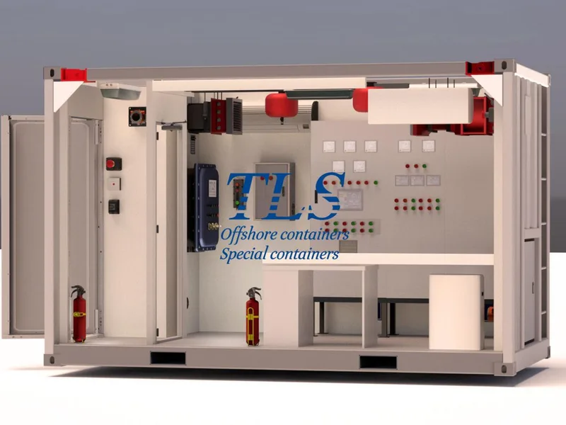
What is a Pressurized Mud Logging Cabin?
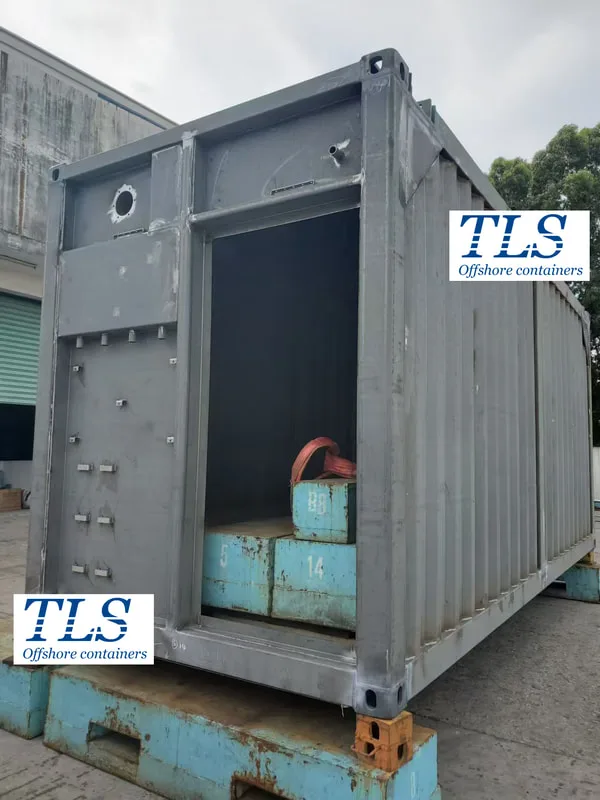
A pressurized mud logging cabin is a specialized container used in drilling operations, particularly in the oil and gas sector. These cabins are engineered to house sensitive equipment and personnel who monitor drilling parameters in real-time. The pressurized environment protects both equipment and operators from hazardous gases and harsh weather conditions, ensuring a safe and effective workspace.
Why Choose TLS Pressurized Mud Logging Cabins?
As a leader in the field, TLS offers state-of-the-art pressurized mud logging cabins that cater to the high demands of the oil and gas industry. Here’s why TLS cabins stand out:
Applications of TLS Pressurized Mud Logging Cabins
TLS Pressurized Mud Logging Cabins are essential in a variety of applications within the oil and gas sector, including:
Conclusion
Investing in a TLS Pressurized Mud Logging Cabin means prioritizing safety, efficiency, and long-term success in the oil and gas industry. Our advanced features, robust construction, and customizable options make these cabins the ideal choice for any drilling operation, whether onshore or offshore.
At TLS, we are committed to helping you achieve your operational goals. Explore how our Pressurized Mud Logging Cabins can be customized to meet your specific needs and enhance the safety and efficiency of your drilling projects.
TLS Offshore Containers / TLS Special Containers is a global supplier of standard and customised containerised solutions.
Wherever you are in the world TLS can help you, please contact us.
Product brochures:
Offshore pressurised mud logging cabin brochure
MCC | Switchgear | VFD | VSD pressurised shelter
Keywords: #Pressurized Mud Logging Cabin, #TLS Mud Logging Cabin, #Oil and Gas Drilling Solutions, #Mud Logging Cabin Safety, #Offshore Drilling Equipment, #Onshore Drilling Solutions, #Real-Time Drilling Data Monitoring, #Customizable Mud Logging Cabins, #Durable Pressurized Cabins, #Advanced Drilling Monitoring Systems, #Hazardous Gas Protection in Drilling
What is a Pressurized Mud Logging Cabin?
A pressurized mud logging cabin is a specialized container used in drilling operations, particularly in the oil and gas sector. These cabins are engineered to house sensitive equipment and personnel who monitor drilling parameters in real-time. The pressurized environment protects both equipment and operators from hazardous gases and harsh weather conditions, ensuring a safe and effective workspace.
Why Choose TLS Pressurized Mud Logging Cabins?
As a leader in the field, TLS offers state-of-the-art pressurized mud logging cabins that cater to the high demands of the oil and gas industry. Here’s why TLS cabins stand out:
- Safety First: At TLS, safety is our top priority. Our cabins are designed to withstand extreme conditions, ensuring the protection of both personnel and equipment. The pressurized environment effectively prevents the infiltration of toxic gases, creating a safer workspace for operators.
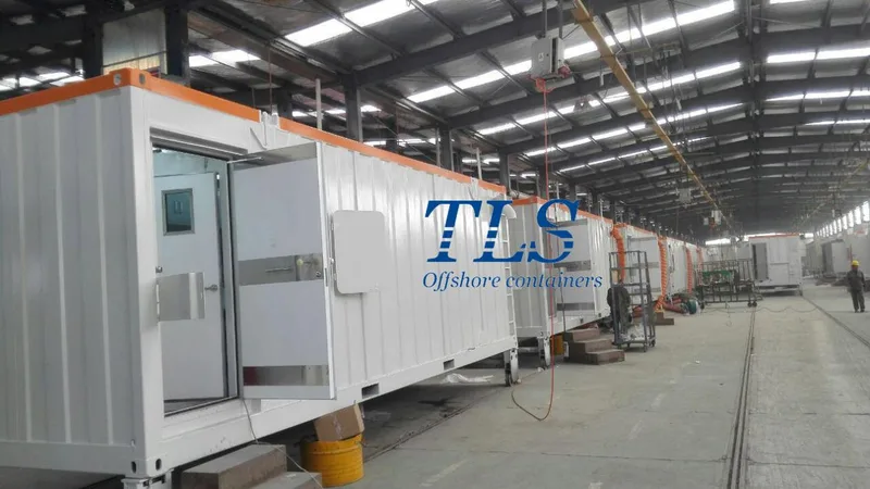
- Durability and Reliability: TLS cabins are constructed with high-grade materials that guarantee long-term durability. Whether deployed onshore or offshore, these cabins are built to perform reliably in the most challenging environments.
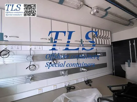
- Advanced Monitoring Systems: TLS mud logging cabins are equipped with the latest technology, providing accurate real-time data on various drilling parameters. This capability enables informed decision-making, enhancing both the efficiency and safety of drilling operations.
- Customization: We understand that every drilling operation has unique needs. That’s why TLS offers customizable solutions. From layout to the integration of specific equipment, our cabins can be tailored to meet the exact requirements of your project.
- Global Compliance: TLS mud logging cabins comply with international safety and environmental standards, ensuring they can be deployed in any region worldwide without legal or regulatory concerns.
Applications of TLS Pressurized Mud Logging Cabins
TLS Pressurized Mud Logging Cabins are essential in a variety of applications within the oil and gas sector, including:
- Exploration Drilling: Accurate data collection during the exploration phase is crucial. TLS cabins ensure that mud loggers can monitor drilling parameters in real-time, leading to more accurate and reliable assessments.
- Offshore Drilling: Offshore environments are notoriously harsh. The robust construction and pressurization of TLS cabins protect equipment and personnel from the elements, ensuring continuous operation in these demanding settings.
- Onshore Drilling: Even in less extreme environments, the reliability and advanced features of TLS mud logging cabins provide a competitive edge, ensuring that operations run smoothly and safely.
Conclusion
Investing in a TLS Pressurized Mud Logging Cabin means prioritizing safety, efficiency, and long-term success in the oil and gas industry. Our advanced features, robust construction, and customizable options make these cabins the ideal choice for any drilling operation, whether onshore or offshore.
At TLS, we are committed to helping you achieve your operational goals. Explore how our Pressurized Mud Logging Cabins can be customized to meet your specific needs and enhance the safety and efficiency of your drilling projects.
TLS Offshore Containers / TLS Special Containers is a global supplier of standard and customised containerised solutions.
Wherever you are in the world TLS can help you, please contact us.
Product brochures:
Offshore pressurised mud logging cabin brochure
MCC | Switchgear | VFD | VSD pressurised shelter
Keywords: #Pressurized Mud Logging Cabin, #TLS Mud Logging Cabin, #Oil and Gas Drilling Solutions, #Mud Logging Cabin Safety, #Offshore Drilling Equipment, #Onshore Drilling Solutions, #Real-Time Drilling Data Monitoring, #Customizable Mud Logging Cabins, #Durable Pressurized Cabins, #Advanced Drilling Monitoring Systems, #Hazardous Gas Protection in Drilling