- Published on
When it comes to managing electrical equipment in hazardous environments, safety, reliability, and compliance are paramount. A 40ft MCC (Motor Control Center) shelter designed for hazardous areas offers the ideal solution to house and protect essential electrical control systems. These shelters are engineered to withstand the harsh conditions often found in industries such as oil and gas, chemicals, and mining. In this blog, we will explore the features, benefits, and key considerations for choosing a 40ft MCC shelter for hazardous areas.
What is an MCC Shelter?
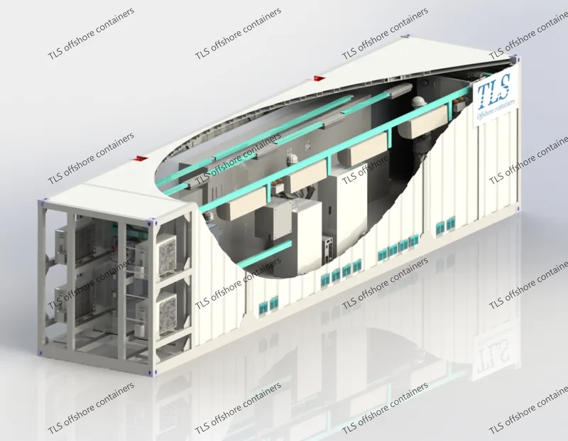
A Motor Control Center (MCC) shelter is a prefabricated enclosure that houses electrical panels, motors, and associated control equipment. These systems are essential for regulating the power supply and ensuring smooth operation of machinery. The shelter protects both personnel and sensitive equipment from external threats, such as extreme weather, dust, moisture, and, importantly, hazardous atmospheres.
In industries like petrochemicals and mining, where explosive or flammable gases and dust may be present, special care must be taken to meet stringent safety standards. A 40ft MCC shelter built for hazardous areas ensures the enclosure is designed and certified to handle these potentially dangerous environments.
Why Choose a 40ft MCC Shelter for Hazardous Areas?
Key Features of a 40ft MCC Shelter for Hazardous Areas
Applications of 40ft MCC Shelters in Hazardous Areas
Conclusion
A 40ft MCC shelter designed for hazardous areas is an essential asset for industries where safety, reliability, and compliance are critical. With their explosion-proof design, robust construction, and adaptability to different environments, these shelters offer the perfect solution for housing motor control systems in high-risk locations. By selecting the right MCC shelter, you can ensure the safety of personnel, protect valuable equipment, and maintain operational efficiency in some of the most challenging environments.
TLS Offshore Containers / TLS Special Containers is a global supplier of standard and customised containerised solutions.
Wherever you are in the world TLS can help you, please contact us.
Product brochures:
Offshore pressurised mud logging cabin brochure
MCC | Switchgear | VFD | VSD pressurised shelter
Keywords: #40ft MCC shelter, #MCC shelter for hazardous areas, #motor control center shelter, #explosion-proof MCC shelter, #hazardous area electrical enclosures, #MCC shelter explosion-proof, #hazardous area shelter solutions, #ATEX certified MCC shelter, #IEC 60079 compliant MCC shelter, #offshore MCC shelter
What is an MCC Shelter?
A Motor Control Center (MCC) shelter is a prefabricated enclosure that houses electrical panels, motors, and associated control equipment. These systems are essential for regulating the power supply and ensuring smooth operation of machinery. The shelter protects both personnel and sensitive equipment from external threats, such as extreme weather, dust, moisture, and, importantly, hazardous atmospheres.
In industries like petrochemicals and mining, where explosive or flammable gases and dust may be present, special care must be taken to meet stringent safety standards. A 40ft MCC shelter built for hazardous areas ensures the enclosure is designed and certified to handle these potentially dangerous environments.
Why Choose a 40ft MCC Shelter for Hazardous Areas?
- Compliance with Safety Standards:
- Explosion-Proof Design:
- Robust Construction:
- Flexibility and Customization:
- Enhanced Safety for Personnel:
Key Features of a 40ft MCC Shelter for Hazardous Areas
- Explosion-Proof Panels and Equipment: The shelter ensures that all electrical panels and equipment housed inside meet hazardous area requirements to avoid the risk of sparks or overheating.
- Ventilation Systems: Proper ventilation is crucial to disperse any heat or gases, preventing the buildup of dangerous atmospheres inside the shelter.
- Fire Suppression Systems: Depending on the risk level, fire suppression systems such as sprinklers or gas-based extinguishing systems may be installed.
- Corrosion-Resistant Materials: Given that hazardous areas often involve exposure to chemicals or seawater, materials used in the construction of the shelter are resistant to corrosion.
- Remote Monitoring Capabilities: Many 40ft MCC shelters come equipped with remote monitoring and control systems that allow for real-time tracking of electrical parameters, temperature, and safety conditions.
Applications of 40ft MCC Shelters in Hazardous Areas
- Oil and Gas Industry: Offshore drilling platforms and onshore refineries require robust, safe solutions for controlling large motors and electrical systems. 40ft MCC shelters provide secure housing for this critical equipment while ensuring safety in explosive environments.
- Chemical Processing Plants: In chemical processing facilities, hazardous chemicals and flammable substances are often present. The 40ft MCC shelter offers a safe and reliable way to manage electrical control equipment in compliance with industry regulations.
- Mining Operations: Mining sites, especially underground mines, face significant risks due to the presence of combustible gases like methane. A 40ft MCC shelter ensures that control equipment remains safe and functional in such high-risk environments.
- Power Generation: For power plants, particularly those in remote locations, a 40ft MCC shelter ensures that electrical equipment continues to operate safely, even in environments with extreme weather conditions or the potential for hazardous atmospheric elements.
Conclusion
A 40ft MCC shelter designed for hazardous areas is an essential asset for industries where safety, reliability, and compliance are critical. With their explosion-proof design, robust construction, and adaptability to different environments, these shelters offer the perfect solution for housing motor control systems in high-risk locations. By selecting the right MCC shelter, you can ensure the safety of personnel, protect valuable equipment, and maintain operational efficiency in some of the most challenging environments.
TLS Offshore Containers / TLS Special Containers is a global supplier of standard and customised containerised solutions.
Wherever you are in the world TLS can help you, please contact us.
Product brochures:
Offshore pressurised mud logging cabin brochure
MCC | Switchgear | VFD | VSD pressurised shelter
Keywords: #40ft MCC shelter, #MCC shelter for hazardous areas, #motor control center shelter, #explosion-proof MCC shelter, #hazardous area electrical enclosures, #MCC shelter explosion-proof, #hazardous area shelter solutions, #ATEX certified MCC shelter, #IEC 60079 compliant MCC shelter, #offshore MCC shelter
Written by Oliver
- Published on
In the demanding environment of oil platforms, ensuring safety and operational efficiency is paramount. One key component in achieving this is the use of specialized equipment designed for hazardous areas. Among these, 40ft pressure containers used in Zone 2 areas are essential for maintaining the integrity and safety of operations. These containers are engineered to withstand the unique challenges posed by the offshore oil and gas industry, providing secure storage and operational support in areas where flammable gases or vapors may be present but are not likely to occur in hazardous quantities under normal operation.
What is Zone 2 on an Oil Platform?
Zone 2 areas are classified as spaces where an explosive gas atmosphere is not likely to occur under normal operating conditions but, if it does occur, will only be present for a short duration. This classification is a part of international safety standards, particularly those set by IEC (International Electrotechnical Commission), to ensure that equipment used in these areas is designed to minimize the risk of ignition in potentially explosive environments.
Pressure containers used in Zone 2 areas are designed with the highest standards of safety, durability, and reliability to prevent any incidents that could endanger lives or disrupt operations. The 40ft pressure container is one of the most commonly used solutions for this purpose due to its robust design, large capacity, and versatility.
Key Features of 40ft Pressure Containers for Zone 2 Areas
Applications of 40ft Pressure Containers in Zone 2 Areas
On an oil platform, 40ft pressure containers are used for various applications, such as:
Why Choose TLS for Your 40ft Pressure Containers?
When selecting a pressure container for Zone 2 areas on oil platforms, quality, compliance, and reliability are non-negotiable. TLS Offshore Containers offer top-tier pressure containers designed specifically for hazardous environments, including Zone 2 areas. With extensive experience in manufacturing safe and durable offshore containers, TLS ensures that every 40ft pressure container meets international safety standards and provides peace of mind in the harshest conditions.
Conclusion
40ft pressure containers designed for Zone 2 areas are indispensable for the safe and efficient operation of oil platforms. With their robust construction, compliance with international safety standards, and ability to safely store and manage hazardous materials, they play a vital role in maintaining safety and operational efficiency. Whether you're storing gases, chemicals, or equipment, choosing the right pressure container is essential. TLS Offshore Containers stands ready to deliver high-quality, compliant pressure containers that will help ensure the safety of both your team and your operations on offshore oil platforms.
If you're looking for reliable, explosion-proof pressure containers for your offshore operations, contact TLS Offshore Containers today and discover the perfect solution for your needs.
TLS Offshore Containers / TLS Special Containers is a global supplier of standard and customised containerised solutions.
Wherever you are in the world TLS can help you, please contact us.
Product brochures:
Offshore pressurised mud logging cabin brochure
MCC | Switchgear | VFD | VSD pressurised shelter
Keywords: #40ft pressure container Zone 2, #Explosion-proof pressure containers, #Pressure containers for offshore platforms, #Zone 2 hazardous area containers, #Offshore oil platform pressure containers, #IECEx certified pressure containers, #ATEX Zone 2 containers, #Explosion-proof containers for oil rigs, #Pressure storage solutions for oil platforms, #40ft pressurized gas containers
What is Zone 2 on an Oil Platform?
Zone 2 areas are classified as spaces where an explosive gas atmosphere is not likely to occur under normal operating conditions but, if it does occur, will only be present for a short duration. This classification is a part of international safety standards, particularly those set by IEC (International Electrotechnical Commission), to ensure that equipment used in these areas is designed to minimize the risk of ignition in potentially explosive environments.
Pressure containers used in Zone 2 areas are designed with the highest standards of safety, durability, and reliability to prevent any incidents that could endanger lives or disrupt operations. The 40ft pressure container is one of the most commonly used solutions for this purpose due to its robust design, large capacity, and versatility.
Key Features of 40ft Pressure Containers for Zone 2 Areas
- Explosion-Proof Construction
- Compliance with IEC and ATEX Standards
- Efficient Pressure Control Systems
- High Capacity for Offshore Operations
- Enhanced Mobility
- Built-in Ventilation and Safety Systems
Applications of 40ft Pressure Containers in Zone 2 Areas
On an oil platform, 40ft pressure containers are used for various applications, such as:
- Storing Pressurized Gases: These containers are often used to store gases under pressure, including natural gas, hydrogen, or other industrial gases that may be required for platform operations.
- Chemical Storage: Offshore platforms require large quantities of chemicals for production, maintenance, and safety purposes. Pressure containers are used to store these chemicals safely, ensuring they are ready for use without posing a hazard to the workers.
- Equipment and Spare Parts Storage: Pressure containers also offer a secure space for storing critical equipment and spare parts, reducing the risk of exposure to harmful elements and ensuring that equipment is easily accessible when needed.
Why Choose TLS for Your 40ft Pressure Containers?
When selecting a pressure container for Zone 2 areas on oil platforms, quality, compliance, and reliability are non-negotiable. TLS Offshore Containers offer top-tier pressure containers designed specifically for hazardous environments, including Zone 2 areas. With extensive experience in manufacturing safe and durable offshore containers, TLS ensures that every 40ft pressure container meets international safety standards and provides peace of mind in the harshest conditions.
Conclusion
40ft pressure containers designed for Zone 2 areas are indispensable for the safe and efficient operation of oil platforms. With their robust construction, compliance with international safety standards, and ability to safely store and manage hazardous materials, they play a vital role in maintaining safety and operational efficiency. Whether you're storing gases, chemicals, or equipment, choosing the right pressure container is essential. TLS Offshore Containers stands ready to deliver high-quality, compliant pressure containers that will help ensure the safety of both your team and your operations on offshore oil platforms.
If you're looking for reliable, explosion-proof pressure containers for your offshore operations, contact TLS Offshore Containers today and discover the perfect solution for your needs.
TLS Offshore Containers / TLS Special Containers is a global supplier of standard and customised containerised solutions.
Wherever you are in the world TLS can help you, please contact us.
Product brochures:
Offshore pressurised mud logging cabin brochure
MCC | Switchgear | VFD | VSD pressurised shelter
Keywords: #40ft pressure container Zone 2, #Explosion-proof pressure containers, #Pressure containers for offshore platforms, #Zone 2 hazardous area containers, #Offshore oil platform pressure containers, #IECEx certified pressure containers, #ATEX Zone 2 containers, #Explosion-proof containers for oil rigs, #Pressure storage solutions for oil platforms, #40ft pressurized gas containers
Written by Oliver
- Published on
Energy Management Systems (EMS) play an increasingly vital role in modern power systems, especially as energy storage solutions and distributed resources continue to expand. By bringing together various hardware and software components, an EMS provides real-time monitoring, decision-making, and control over the charging and discharging of energy storage assets. Below is an in-depth look at EMS architecture, core functionalities, and how these systems adapt to different scenarios.
EMS Architecture Overview
1. Device Layer
The device layer includes essential energy conversion and management units such as the Power Conversion System (PCS) and the Battery Management System (BMS). These components collect real-time data on battery voltage, current, temperature, and state of charge (SOC). They also track PCS parameters like power output and operational status. All this raw data forms the foundation on which the EMS builds its decision-making processes.
2. Communication Layer
This layer addresses link stability, protocols, and data transfer. Common standards include CAN bus and Modbus, both of which enable various components—PCS, BMS, sensors, and more—to exchange data reliably. High-volume systems, such as large-scale energy storage plants, require stable, rapid data transmission to ensure the EMS receives updates quickly and issues timely control commands.
3. Information Layer
Comprising middleware, databases, and servers, this layer handles the storage and processing of real-time and historical data. By archiving parameters—such as battery performance and charging records—operators can analyze trends, predict maintenance needs, and fine-tune operational strategies. This secure data repository also supports efficient reporting and long-term performance evaluations.
4. Application Layer
The top layer includes user-facing interfaces like web portals or mobile apps, offering visual dashboards for system monitoring, control, data analytics, and fault diagnosis. Through these interfaces, operators can adjust charging schedules, generate custom reports, and set economic operation strategies (e.g., charging at off-peak hours and discharging during peak demand). They can also perform real-time control, ensuring a swift response to unexpected events.
Core EMS Functions
1. Real-Time Monitoring
An EMS continuously gathers operational parameters across the system—battery voltage, current, SOC, SOH, power output, and load metrics. If any reading deviates from preset thresholds, the EMS triggers alerts, allowing immediate investigation and intervention.
2. Comprehensive Data Visualization
Historical and real-time data, including energy flows, battery health trends, and economic returns, can be viewed in customizable dashboards. This level of detail helps decision-makers track performance over time and analyze effectiveness of various strategies.
3. Economic Operation Strategies
By evaluating factors like time-of-use electricity pricing, load demands, and renewable energy forecasts, the EMS sets the optimal charge/discharge schedule. Charging at low-cost, off-peak times and discharging during peak periods helps reduce costs or even generate revenue in market-participating scenarios. Such strategies are particularly useful in microgrids where renewable energy sources, like solar or wind, must be balanced with storage to ensure consistency and cost-effectiveness.
4. Fault Alarms and Event Logging
The EMS logs alarms and categorizes them by severity. Critical issues—such as severe temperature spikes or abnormal battery voltages—are flagged in red, signaling the need for urgent resolution. These detailed logs help operators track problems over time, identify root causes, and prevent recurrences.
5. Energy Dispatch and Scheduling
Using real-time data on load, battery SOC, and grid prices, the EMS optimizes power flows. During low-demand, low-price periods, the system stores energy; during peaks or supply shortages, it discharges to maintain balance. This scheduling enhances system stability and supports grid services like frequency regulation.
Different EMS Scenarios
• Source/Utility-Side Storage
Often designed with a local control station, source-side EMS focuses on grid-level services such as regulating frequency and voltage. Large wind or solar farms rely on EMS functionality to decide when to store excess energy or feed it into the grid, ensuring stability and maximum renewable energy utilization.
• Commercial and Industrial Storage
Due to smaller capacities spread across multiple sites, C&I scenarios require remote monitoring. Here, EMS solutions integrate seamlessly with cloud-based platforms, offering centralized control of numerous distributed facilities. The primary goals are reducing energy bills (by peak shaving), providing backup power, and ensuring swift adjustments to changing load requirements.
Conclusion
Energy Management Systems provide the backbone for modern energy storage solutions, uniting hardware and software components into a cohesive whole. By monitoring system metrics, executing economic dispatch strategies, and furnishing real-time control interfaces, an EMS optimizes both reliability and profitability—whether at the grid level or in commercial and industrial settings. As the energy landscape evolves, the EMS will remain a linchpin for integrating diverse resources, reducing operational costs, and strengthening overall power stability.
- Published on
Gaining insight into the key performance parameters of energy storage batteries is crucial for understanding how they are used and how they perform within a storage system. Below is an explanation of several main parameters:
1. Cycle Life
This refers to the number of times the battery can be fully charged and discharged. The length of the cycle life is directly related to the battery’s durability and usage cost. For instance, in scenarios requiring long-term stable energy storage, batteries with a long cycle life are needed. Under proper usage conditions, lithium iron phosphate (LFP) batteries can achieve a high number of cycles. However, some batteries (such as ternary lithium batteries) have faster capacity degradation and shorter lifespans, affecting their suitability for long-term energy storage projects.
2. Capacity
Typically expressed in ampere-hours (Ah). The energy (Wh) can be calculated as Power (W) × Hours (h) = Voltage (V) × Ampere-hours (Ah). For example, a 48V100Ah battery indicates a capacity of 4.8 kWh. The capacity determines how much energy can be stored in a single charge. When selecting a battery, one should consider specific storage needs. For home energy storage systems, factors such as household electricity consumption and the desired duration of stored power should be taken into account to determine the appropriate battery capacity.
3. Charge/Discharge Efficiency
This refers to the energy conversion efficiency during the charging and discharging process. The charge/discharge rate (C-rate) equals the charge or discharge current divided by the rated capacity. For example, if a 100Ah battery is discharged at 15A, the discharge rate is 0.15C. Charging and discharging efficiency affects energy loss during these processes. A high-efficiency battery uses energy more effectively during charging and discharging, reducing waste and significantly contributing to the overall economics and performance of an energy storage system.
4. Depth of Discharge (DOD)
This is the percentage of the battery’s rated capacity that is actually discharged. For the same battery, a deeper DOD typically results in a shorter cycle life. Improving one aspect of performance can often compromise another. For example, at 80% DOD, lithium batteries may achieve 6,000–12,000 cycles. Therefore, in actual use, controlling the depth of discharge properly is necessary to prolong battery life.
5. State of Charge (SOC)
This represents the percentage of remaining battery capacity relative to its rated capacity. An SOC of 0% means the battery is completely discharged, while an SOC of 100% means it is fully charged. As an important parameter in a Battery Management System (BMS), SOC helps reflect remaining battery capacity and operating status in real time. This allows users to understand the current power level and plan charging and discharging more effectively.
6. State of Health (SOH)
This encompasses factors such as capacity, power, and internal resistance. It is defined as the ratio of the battery’s capacity—when discharged from full charge at a certain rate down to its cutoff voltage—to its nominal capacity. In simpler terms, it is the ratio of the battery’s current performance parameters to its rated parameters after some period of use. A brand-new battery is 100% SOH, while a fully degraded battery is 0%. According to IEEE standards, if, after some time in service, the fully charged capacity is less than 80% of the rated capacity, the battery should be replaced. Monitoring SOH helps detect performance decline early, allowing timely action.
Battery Safety and Environmental Considerations
Safety and environmental concerns cannot be overlooked when using batteries. Below are some relevant points and corresponding measures:
1. Safety Risks and Preventive Measures: Overcharge and Over-Discharge
Lithium batteries used improperly—such as being overcharged or exposed to high temperatures or impacts—can undergo internal thermochemical reactions, resulting in thermal runaway. If thermal runaway propagates within a battery module, it can cause a system-level fire. Additionally, toxic and flammable gases may be released, making firefighting difficult. To prevent such risks, choose batteries that comply with relevant safety standards (e.g., IEC62619). At the same time, the Battery Management System (BMS) plays a key role and should be certified under IEC61508 to ensure the battery does not operate beyond its limits. Some storage systems also adopt multi-stage charging (three-stage charging), including constant current, constant voltage, and float charging, to improve safety and avoid overcharging.
2. Battery Module Safety Integration Risks
Battery modules and racks should meet the requirements of UL1973 and IEC62619. Selecting batteries certified by UL9540A means they have been tested to simulate thermal runaway and to check whether a fire would spread. Batteries should be installed in sturdy battery cabinets that keep each unit separate, helping to prevent a fire from spreading to other cabinets. The cabinet housing should have high fire resistance and provide thermal insulation to keep batteries within a suitable temperature range (typically 20°C to 23°C).
- Published on
Power Conversion Systems (PCS) are critical components in energy storage systems. Acting as a “bridge” that switches electrical energy between direct current (DC) and alternating current (AC), PCS enable efficient charging and discharging of batteries for a wide variety of applications. From large-scale renewable energy stations to industrial facilities and even household setups, PCS play a pivotal role in ensuring seamless energy transitions and stable power delivery.
Core Function of PCS
At its heart, a PCS facilitates bidirectional power flow. During charging, it converts AC power from the grid into DC power suitable for the energy storage battery. This capability is especially beneficial in scenarios such as off-peak periods or times when electricity prices are low; the excess or cheaper electricity can be stored in batteries for future use. Conversely, during discharge, the PCS inverts the battery’s DC power back to AC for general consumption or for feeding back into the grid. This is advantageous during periods of peak demand or when the grid experiences a shortfall, allowing stored energy to support critical loads and maintain uninterrupted power supply.
Moreover, in remote or off-grid environments, a PCS can autonomously supply AC power to connected loads without any reliance on the traditional utility grid. This flexibility underlines why PCS technology is indispensable across diverse energy storage deployments.
Key Components and Principles
A typical PCS comprises multiple elements, including inverters and rectifiers, which collaborate to manage AC-DC conversion. Inverters handle the DC-to-AC process when discharging power to loads or the grid, ensuring the output power meets specific voltage, frequency, and waveform requirements. Rectifiers, on the other hand, manage AC-to-DC conversion during charging, enabling the battery to store excess power.
Technically, PCS operation is founded on four-quadrant control principles, meaning the system can handle both active and reactive power management across all quadrants of the power plane. This design lets it stabilize volatile energy inputs (such as wind or solar), ensuring smoother power output and enhanced reliability. Consequently, renewable energy sources become more predictable, boosting their integration into the broader energy ecosystem.
Applications Across Different Scales
1. Large-Scale Energy Storage:
In utility-scale installations, PCS solutions often operate in the megawatt (MW) range or higher. These systems balance grid supply and demand, stabilize voltage and frequency, and smooth out the intermittent nature of wind and solar farms. For example, a large solar farm might store daytime excess solar power via a PCS-equipped battery system, then discharge it at night or during cloudy periods. Moreover, large PCS setups can work in tandem with conventional power plants for fast frequency regulation, enhancing grid stability.
2. Commercial and Industrial Settings:
Commercial and industrial (C&I) users often deploy PCS with power ratings spanning tens of kilowatts (kW) to several megawatts. By charging during low-cost, off-peak hours and discharging during expensive peak hours, businesses can significantly reduce electricity bills through peak shaving. In the event of grid disturbances, the stored energy—converted via PCS—protects sensitive equipment and maintains continuity. Data centers, for instance, can benefit greatly from this approach by ensuring reliable backup power.
3. Residential Energy Storage:
Smaller PCS units, usually in the range of a few kW to around 15 kW, are common in home-based energy storage solutions. These systems pair effectively with rooftop solar panels: the PCS inverts DC power from solar modules to AC for household use, stores any surplus in the battery, and provides backup power in case of outages. By optimizing self-consumption and offering reliable emergency power, homeowners gain both energy independence and cost savings.
Influencing Factors for PCS Selection
When selecting a PCS, system size is a primary consideration: larger systems need higher power ratings, whereas smaller-scale, household systems call for lower capacity. The required power quality—voltage precision, frequency regulation, and response time—further dictates PCS design. Operating environment (temperature, humidity, and enclosure requirements), budget constraints, and compatibility with batteries or monitoring systems all factor into the final choice. Balancing these considerations ensures that the PCS operates at peak performance, supporting stable and efficient energy storage operations.
In conclusion, Power Conversion Systems are indispensable for modern energy storage solutions. By effectively linking DC and AC power, they enable flexible charging, reliable discharging, and stable grid interaction. As more industries and households embrace renewable energy, the role of PCS continues to expand, providing greater energy security, cost savings, and environmental benefits for all.
- Published on
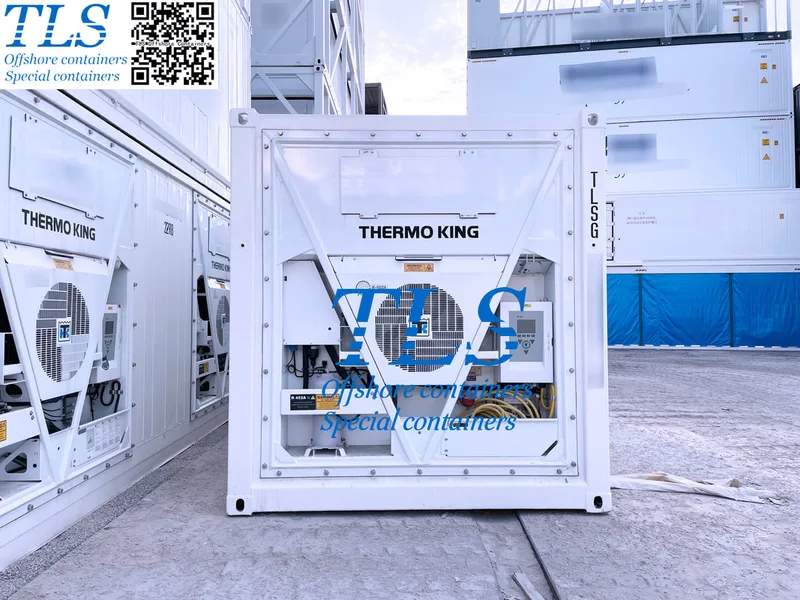
In the refrigeration industry, DAIKIN, CARRIER, and THERMO KING stand out as leaders, each excelling in distinct applications. For hazardous goods, chemicals, and pharmaceuticals requiring stringent temperature control, dual refrigeration systems play a crucial role in ensuring safety and reliability. This blog compares these brands and highlights their suitability for transporting sensitive cargo.
Leading Refrigeration Brands1. DAIKIN
② VRV Systems: Offers advanced multi-zone temperature control.
③ Noise Reduction: Ideal for noise-sensitive environments.
② Flexible System Designs: Adaptable to a wide range of industrial applications.
③ Regulatory Compliance: Meets global standards like IATA DGR, ADR, and GDP.
② Precise Temperature Management: Guarantees high accuracy during transport.
③ Durability and Efficiency: Built for long-distance, fuel-efficient operations.
The Importance of Dual Refrigeration SystemsThe transportation of hazardous goods, chemicals, and pharmaceuticals demands strict temperature control and safety standards. Dual refrigeration systems, with their redundancy and precision, provide a reliable solution to maintain cargo integrity, even in the event of a system failure.
THERMO KING Dual Refrigeration Systems
②High Reliability: Ensures uninterrupted operation if one unit fails.
③Remote Monitoring: Real-time temperature and system status tracking.
CARRIER Dual Refrigeration Systems
② Multi-Mode Operation: Independent control of multiple temperature zones for mixed cargo.
③ Regulatory Compliance: Adheres to international standards, ensuring safe transport.
Conclusion
When transporting hazardous goods, chemicals, or pharmaceuticals, selecting a reliable dual refrigeration system is critical for ensuring cargo safety and maintaining quality. THERMO KING and CARRIER offer excellent options tailored to different needs, making them indispensable in cold chain logistics. Evaluate your specific transportation requirements to make the best choice and achieve optimal performance.
TLS Offshore Containers / TLS Special Containers is a global supplier of standard and customised containerised solutions.
Wherever you are in the world TLS can help you, please contact us.
Any more information regarding Offshore Reefer container, ISO reefer container, please download TLS offshore reefer containers brochure for your reference
Keywords:#Refrigeration Industry,#DAIKIN,#THERMO KING,#Temperature Control,#Dual Refrigeration Systems,#Hazardous Goods,#Pharmaceuticals,#Cold Chain Logistics,#Eco-Friendly Refrigerants,#Multi-Zone Temperature Control,#Regulatory Compliance,
#Cold Storage,#Transport Refrigeration,#Precision Temperature Management,#Remote Monitoring,#Long-Distance Transport
Leading Refrigeration Brands1. DAIKIN
- Primary Focus: Residential and commercial refrigeration (temperature range: -20°C to 10°C).
- Key Features:
② VRV Systems: Offers advanced multi-zone temperature control.
③ Noise Reduction: Ideal for noise-sensitive environments.
- Typical Applications: High-end residential buildings, offices, and supermarkets requiring efficient heating, cooling, and refrigeration.
- Primary Focus: Commercial and industrial refrigeration, particularly cold chain logistics (temperature range: -30°C to 10°C).
- Key Features:
② Flexible System Designs: Adaptable to a wide range of industrial applications.
③ Regulatory Compliance: Meets global standards like IATA DGR, ADR, and GDP.
- Typical Applications: Cold storage warehouses, logistics transportation, and large-scale commercial facilities.
- Primary Focus: Transportation refrigeration (temperature range: -30°C to 10°C).
- Key Features:
② Precise Temperature Management: Guarantees high accuracy during transport.
③ Durability and Efficiency: Built for long-distance, fuel-efficient operations.
- Typical Applications: Refrigerated trucks, trailers, and containers for pharmaceuticals and hazardous goods.
The Importance of Dual Refrigeration SystemsThe transportation of hazardous goods, chemicals, and pharmaceuticals demands strict temperature control and safety standards. Dual refrigeration systems, with their redundancy and precision, provide a reliable solution to maintain cargo integrity, even in the event of a system failure.
THERMO KING Dual Refrigeration Systems
- Solutions: Offers advanced Dual Temp Systems with multi-zone and redundancy features.
- Key Benefits:
②High Reliability: Ensures uninterrupted operation if one unit fails.
③Remote Monitoring: Real-time temperature and system status tracking.
- Applications: Long-distance transport of hazardous chemicals, pharmaceuticals, and temperature-sensitive goods.
CARRIER Dual Refrigeration Systems
- Solutions: Features the Vector series, including Vector HE 19 and Vector 1950 MT.
- Key Benefits:
② Multi-Mode Operation: Independent control of multiple temperature zones for mixed cargo.
③ Regulatory Compliance: Adheres to international standards, ensuring safe transport.
- Applications: High-safety transport of chemicals and pharmaceuticals in compliance-driven environments.
- THERMO KING: Best suited for high-precision, long-distance transportation of hazardous goods and temperature-sensitive pharmaceuticals.
- CARRIER: Ideal for large-scale, compliance-focused cold chain logistics, particularly in industrial settings.
Conclusion
When transporting hazardous goods, chemicals, or pharmaceuticals, selecting a reliable dual refrigeration system is critical for ensuring cargo safety and maintaining quality. THERMO KING and CARRIER offer excellent options tailored to different needs, making them indispensable in cold chain logistics. Evaluate your specific transportation requirements to make the best choice and achieve optimal performance.
TLS Offshore Containers / TLS Special Containers is a global supplier of standard and customised containerised solutions.
Wherever you are in the world TLS can help you, please contact us.
Any more information regarding Offshore Reefer container, ISO reefer container, please download TLS offshore reefer containers brochure for your reference
Keywords:#Refrigeration Industry,#DAIKIN,#THERMO KING,#Temperature Control,#Dual Refrigeration Systems,#Hazardous Goods,#Pharmaceuticals,#Cold Chain Logistics,#Eco-Friendly Refrigerants,#Multi-Zone Temperature Control,#Regulatory Compliance,
#Cold Storage,#Transport Refrigeration,#Precision Temperature Management,#Remote Monitoring,#Long-Distance Transport

Written by Snowy
- Published on
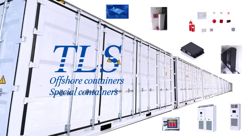
Key Considerations in Energy Storage Container Design The demand for energy storage solutions has surged as renewable energy technologies, such as solar and wind power, become increasingly integrated into global energy systems. Battery Energy Storage Systems (BESS) are crucial in managing the variability of renewable energy sources, and energy storage containers provide an efficient, scalable way to house these systems. Designing a robust, high-performance energy storage container is critical to ensuring safety, efficiency, and cost-effectiveness. In this blog, we explore the key factors that must be considered when designing an energy storage container.
1. Battery Type and Configuration
The foundation of any energy storage system lies in the choice of battery technology. Lithium-ion batteries are the most popular due to their high energy density, long lifespan, and efficiency, but alternatives like lead-acid and flow batteries may also be considered depending on the application. The battery configuration must be carefully designed to optimize the system’s capacity while ensuring ease of maintenance, safe operation, and efficient thermal management.
2. Safety Design
Given the high energy densities involved, safety is paramount in the design of energy storage containers. Several features are essential to prevent accidents:
3. Electrical Systems Integration
The Battery Management System (BMS) plays a critical role in managing battery health by monitoring important metrics like voltage, temperature, and charge levels. The inverter and power electronics must also be selected carefully to facilitate efficient DC to AC conversion, ensuring smooth energy delivery to the grid or other power systems.
In addition, high-quality cabling and connectors are vital for safe and efficient power distribution within the container.
4. Environmental Adaptability
Energy storage systems often operate in a range of environments, from extreme heat to cold. The design must account for environmental factors like:
5. Capacity, Space, and Scalability
Maximizing space efficiency is essential to increase the energy density of the container. Thoughtful layout planning should ensure that the system can house the necessary components, such as batteries, inverters, and cooling systems, without overcrowding. Modular designs allow the system to scale as future energy demands increase or technologies evolve.
6. Grid Integration and Power Management
The design must also account for the system’s ability to connect seamlessly to the power grid or off-grid applications. It should support grid stabilization, demand-response programs, and energy management systems (EMS) to ensure efficient energy transfer and storage.
For off-grid installations, backup power capabilities and islanding protection should also be integrated to safeguard against grid outages.
7. Remote Monitoring and Smart Management
As with any modern system, remote monitoring capabilities are critical. The integration of an intelligent management system enables operators to track real-time data, perform diagnostics, and receive maintenance alerts. Predictive analytics can optimize performance by anticipating issues before they arise, reducing downtime and improving system efficiency.
8. Transportability and Logistics
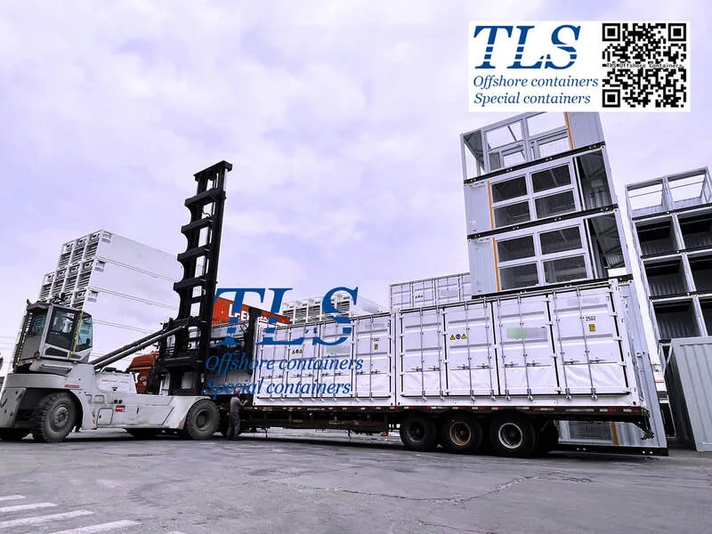
Energy storage containers should be designed with logistical considerations in mind. Adhering to standard shipping dimensions ensures the system can be transported by road, rail, or sea without complications. The container must also be durable enough to withstand the rigors of transportation while keeping the internal equipment safe.
9. Maintainability
A well-designed container should allow for easy maintenance and component replacement. Modular components and accessible layouts reduce downtime during maintenance cycles and make repairs more cost-effective.
10. Cost Efficiency
While it’s important to deliver high-quality performance, the design must also remain cost-effective. Striking a balance between performance and cost is key to ensuring the energy storage system remains competitive in the market. This includes selecting cost-efficient materials, avoiding over-engineering, and focusing on modular designs to allow for flexibility and future upgrades.
Conclusion
Designing an energy storage container is a complex process that requires careful attention to numerous technical, environmental, and logistical factors. Safety, efficiency, and scalability must be balanced to ensure that the energy storage system can provide reliable, long-term performance. As demand for renewable energy solutions continues to rise, well-designed energy storage systems will play a pivotal role in stabilizing power grids, reducing carbon footprints, and advancing the global transition to clean energy.
TLS Offshore Containers / TLS Special Containers is a global supplier of standard and customised containerised solutions.
Wherever you are in the world TLS can help you, please contact us.
Regarding the Battery Energy Storage System (BESS) container, please download Energy Storage System (ESS) Containers brochure for reference.
Keywords:#Energy Storage Container Design,#Battery Energy Storage Systems (BESS),#Battery Management System (BMS),#Thermal Management,#Fire Suppression Systems,#Cooling Systems,#Ingress Protection (IP) Ratings,#Modular Design,#Grid Integration,#Power Electronics,#Remote Monitoring,#Energy Management Systems (EMS),#Energy Storage System Safety,#Energy Storage System Scalability,#Logistical Considerations for Energy Storage,#Cost Optimization in Energy Storage Design,#Renewable Energy Storage Solutions,#Lithium-ion Battery Design,#Energy Storage System Maintenance.
1. Battery Type and Configuration
The foundation of any energy storage system lies in the choice of battery technology. Lithium-ion batteries are the most popular due to their high energy density, long lifespan, and efficiency, but alternatives like lead-acid and flow batteries may also be considered depending on the application. The battery configuration must be carefully designed to optimize the system’s capacity while ensuring ease of maintenance, safe operation, and efficient thermal management.
2. Safety Design
Given the high energy densities involved, safety is paramount in the design of energy storage containers. Several features are essential to prevent accidents:
- Fire and Explosion Prevention: Energy storage systems, particularly lithium-ion batteries, can be prone to thermal runaway, posing fire risks. Therefore, integrating fire suppression systems, fire-resistant barriers, and temperature regulation mechanisms is crucial.
- Thermal Management: Battery performance can be severely impacted by excessive heat, so an effective cooling system (liquid cooling or air cooling) is required to maintain optimal temperatures for battery health and safety.
- Ingress Protection: The container must be designed to prevent the entry of water, dust, or any foreign particles that could damage internal components. IP (Ingress Protection) ratings ensure that the system can function under various environmental conditions.
3. Electrical Systems Integration
The Battery Management System (BMS) plays a critical role in managing battery health by monitoring important metrics like voltage, temperature, and charge levels. The inverter and power electronics must also be selected carefully to facilitate efficient DC to AC conversion, ensuring smooth energy delivery to the grid or other power systems.
In addition, high-quality cabling and connectors are vital for safe and efficient power distribution within the container.
4. Environmental Adaptability
Energy storage systems often operate in a range of environments, from extreme heat to cold. The design must account for environmental factors like:
- Temperature Extremes: Insulation or heating elements might be required in colder climates to protect the system.
- Corrosion Resistance: For installations in coastal or industrial areas, anti-corrosion materials like galvanized steel or aluminum alloys must be used.
- Structural Integrity: The container should withstand harsh weather conditions, including high winds or seismic activity. Reinforced structures and shockproof designs ensure stability in adverse conditions.
5. Capacity, Space, and Scalability
Maximizing space efficiency is essential to increase the energy density of the container. Thoughtful layout planning should ensure that the system can house the necessary components, such as batteries, inverters, and cooling systems, without overcrowding. Modular designs allow the system to scale as future energy demands increase or technologies evolve.
6. Grid Integration and Power Management
The design must also account for the system’s ability to connect seamlessly to the power grid or off-grid applications. It should support grid stabilization, demand-response programs, and energy management systems (EMS) to ensure efficient energy transfer and storage.
For off-grid installations, backup power capabilities and islanding protection should also be integrated to safeguard against grid outages.
7. Remote Monitoring and Smart Management
As with any modern system, remote monitoring capabilities are critical. The integration of an intelligent management system enables operators to track real-time data, perform diagnostics, and receive maintenance alerts. Predictive analytics can optimize performance by anticipating issues before they arise, reducing downtime and improving system efficiency.
8. Transportability and Logistics
Energy storage containers should be designed with logistical considerations in mind. Adhering to standard shipping dimensions ensures the system can be transported by road, rail, or sea without complications. The container must also be durable enough to withstand the rigors of transportation while keeping the internal equipment safe.
9. Maintainability
A well-designed container should allow for easy maintenance and component replacement. Modular components and accessible layouts reduce downtime during maintenance cycles and make repairs more cost-effective.
10. Cost Efficiency
While it’s important to deliver high-quality performance, the design must also remain cost-effective. Striking a balance between performance and cost is key to ensuring the energy storage system remains competitive in the market. This includes selecting cost-efficient materials, avoiding over-engineering, and focusing on modular designs to allow for flexibility and future upgrades.
Conclusion
Designing an energy storage container is a complex process that requires careful attention to numerous technical, environmental, and logistical factors. Safety, efficiency, and scalability must be balanced to ensure that the energy storage system can provide reliable, long-term performance. As demand for renewable energy solutions continues to rise, well-designed energy storage systems will play a pivotal role in stabilizing power grids, reducing carbon footprints, and advancing the global transition to clean energy.
TLS Offshore Containers / TLS Special Containers is a global supplier of standard and customised containerised solutions.
Wherever you are in the world TLS can help you, please contact us.
Regarding the Battery Energy Storage System (BESS) container, please download Energy Storage System (ESS) Containers brochure for reference.
Keywords:#Energy Storage Container Design,#Battery Energy Storage Systems (BESS),#Battery Management System (BMS),#Thermal Management,#Fire Suppression Systems,#Cooling Systems,#Ingress Protection (IP) Ratings,#Modular Design,#Grid Integration,#Power Electronics,#Remote Monitoring,#Energy Management Systems (EMS),#Energy Storage System Safety,#Energy Storage System Scalability,#Logistical Considerations for Energy Storage,#Cost Optimization in Energy Storage Design,#Renewable Energy Storage Solutions,#Lithium-ion Battery Design,#Energy Storage System Maintenance.
Written by Snowy
- Published on
A Battery Management System (BMS) plays a crucial role in modern energy storage and electrification applications. It oversees a battery pack’s operational health, protects it against hazards, and ensures optimal performance through various monitoring and control functions. By assessing parameters such as voltage, current, temperature, and state-of-charge, a BMS safeguards both the battery pack and connected systems, making it indispensable in fields ranging from electric vehicles to large-scale energy storage.
Key Concepts and Role of a BMS
A BMS’s primary goals are to extend battery life, prevent overcharging and over-discharging, and monitor battery status for safety. Acting like a “trusted caretaker,” it collects real-time data—individual cell voltages, loop current, cell and module temperatures, system insulation resistance—and performs dynamic analyses. These measurements feed into protective strategies that keep the battery pack in its ideal operating range, mitigating risks such as thermal runaway or sudden capacity loss. By preventing conditions that degrade cells prematurely, the BMS maintains system reliability, ensuring longer service life and stable operation.
Core Functions of a BMS
1. Real-Time Monitoring
• Voltage: Each cell’s voltage is continuously checked to avert scenarios like overcharge or over-discharge, which can harm both the battery and connected equipment.
• Current: Charging and discharging current are tracked to ensure values remain within safe limits, preventing overheating and potential safety hazards.
• Temperature: Since temperature significantly influences battery performance, the BMS monitors each cell or module. Excessive heat can lead to thermal runaway, while low temperatures hinder battery efficiency.
• Insulation Resistance: Monitoring insulation levels helps detect electrical leaks or faults that pose safety risks to the system and nearby personnel.
2. State Estimation
• State of Charge (SOC): Through data analysis and algorithms, the BMS accurately estimates remaining battery capacity, guiding decisions on charging schedules and usage duration.
• State of Health (SOH): The system evaluates overall battery health, predicting remaining life. This advanced warning helps schedule maintenance, minimizing downtime and unexpected failures.
• State of Power (SOP): Knowing the maximum power a battery can deliver at any moment aids in managing loads and preventing overloading.
• State of Energy (SOE): Estimating available energy further refines scheduling and energy dispatch for improved system efficiency.
3. Control and Management
• Charge/Discharge Management: Based on SOC, SOH, and other parameters, the BMS regulates current and voltage to avert overcharging or over-discharging. This extends battery lifespan and ensures stable performance.
• Cell Balancing: Employing active or passive balancing methods, the BMS equalizes each cell’s voltage and capacity. This process enhances consistency across the entire pack, improving both efficiency and safety.
• Thermal Management: By interfacing with cooling or heating subsystems, the BMS maintains cells within an optimal temperature range, reducing the likelihood of performance drops or safety incidents.
• Fault Diagnosis and Protection: The BMS identifies issues like short circuits, open circuits, and overheating. Upon detecting a fault, it initiates protective actions—such as disconnecting the battery—to preserve the system’s integrity.
4. Communication Management
BMS devices commonly interact with Power Conversion Systems (PCS), Energy Management Systems (EMS), or other equipment through interfaces like CAN bus or Modbus. In more complex setups, wireless communication offers remote monitoring, crucial for extensive battery banks or hard-to-reach locations. This data exchange fosters integrated control, ensuring each subsystem works cohesively and meets safety standards.
BMS Architectures
1. Centralized BMS:
All monitoring and control occur via a single controller board, reducing costs and communication overhead. This arrangement is simple but may pose reliability challenges, as a single point of failure can compromise the entire system.
2. Distributed BMS:
Multiple slave modules collect data from cells, with a master controller overseeing coordination. This design offers higher reliability, ease of maintenance, and flexibility, though it involves added complexity and cost.
3. Modular BMS:
Battery cells are grouped into modules, each with its own monitoring and control functions. While it balances cost, reliability, and scalability, communication loads can be heavier, and maintenance may become more involved depending on the module design.
Conclusion
A Battery Management System is much more than a mere monitoring device: it ensures the safety, longevity, and efficiency of modern battery-powered systems. By offering real-time data gathering, precise state estimation, control, and communication, a BMS enables energy storage setups—whether in electric vehicles, residential battery packs, or massive grid-scale plants—to operate securely and effectively. As battery technology evolves, so too will the critical role played by robust, intelligent BMS solutions, ensuring power systems remain reliable, cost-effective, and environmentally friendly.
- Published on
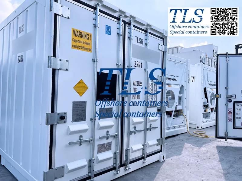
TLS ISO reefer & refrigerated container: Dimensions, Uses, and Working Principles
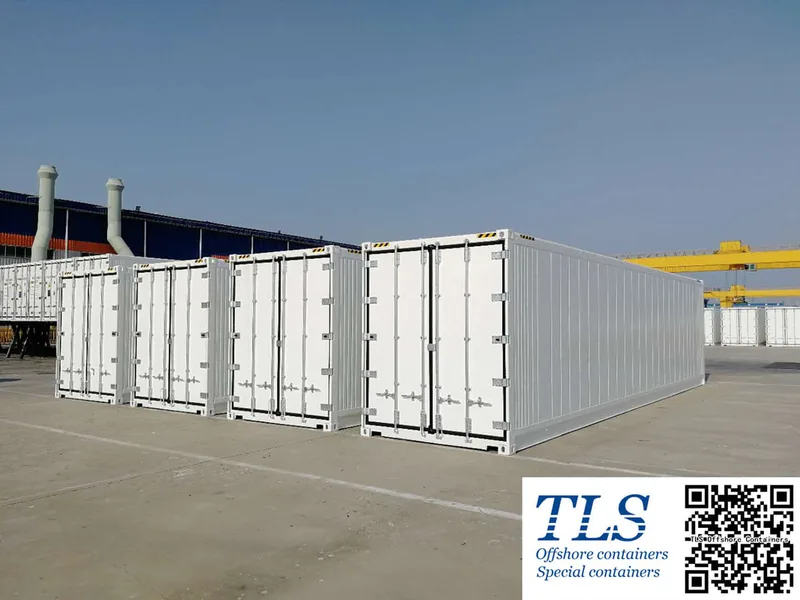
Refrigerated container (commonly referred to as "reefers") play a vital role in transporting temperature-sensitive and perishable goods, ensuring their freshness and quality during long-distance transportation. This blog explores the uses, working principles, and essential knowledge about these containers.
What is the TLS refrigerated container?Reefer container is a large refrigeration unit capable of maintaining temperatures between -20°C and +2°C.(This temperature range is usually sufficient) By connecting to a power source, the refrigeration system injects cool air to maintain a consistent temperature inside the container, preserving the integrity of the goods.
Primary Uses of Container RefrigeratorsReefers are ideal for transporting goods that require low-temperature storage. Commonly transported items include:
Working Principles of Container Refrigerators
How to Properly Stow Cargo
Proper stowage of goods is crucial for the effective operation of a reefer:
Conclusion
Container refrigerators provide a reliable solution for temperature-controlled transportation, suitable for a variety of goods ranging from frozen foods to fresh produce. Understanding their working principles and proper operation can significantly improve logistics efficiency and maintain cargo quality.
TLS Offshore Containers / TLS Special Containers is a global supplier of standard and customised containerised solutions.
Wherever you are in the world TLS can help you, please contact us.
Any more information regarding Offshore Reefer container, ISO reefer container, please download TLS offshore reefer containers brochure for your reference
Keywords: #TLS container refrigerators,#Reefer containers,#Refrigerated container dimensions,#Temperature-controlled shipping,#Perishable goods transportation,#Refrigeration systems,#Cold storage logistics,#ISO container specifications,#Container ventilation system,#Container humidity control,#Cargo pre-cooling,#Reefer power supply,#T-shaped grooves,#Drainage system in containers,#Food and beverage shipping,#Frozen goods logistics,#Standard reefer sizes,#20-foot refrigerated container,#40-foot reefer container
Refrigerated container (commonly referred to as "reefers") play a vital role in transporting temperature-sensitive and perishable goods, ensuring their freshness and quality during long-distance transportation. This blog explores the uses, working principles, and essential knowledge about these containers.
What is the TLS refrigerated container?Reefer container is a large refrigeration unit capable of maintaining temperatures between -20°C and +2°C.(This temperature range is usually sufficient) By connecting to a power source, the refrigeration system injects cool air to maintain a consistent temperature inside the container, preserving the integrity of the goods.
Primary Uses of Container RefrigeratorsReefers are ideal for transporting goods that require low-temperature storage. Commonly transported items include:
- Food Products: Frozen meat, fresh meat, seafood, fruits, vegetables, dairy products, and pickled foods.
- Beverages: Juices, wines, and other drinks.
- Others: Special temperature-controlled goods.
Working Principles of Container Refrigerators
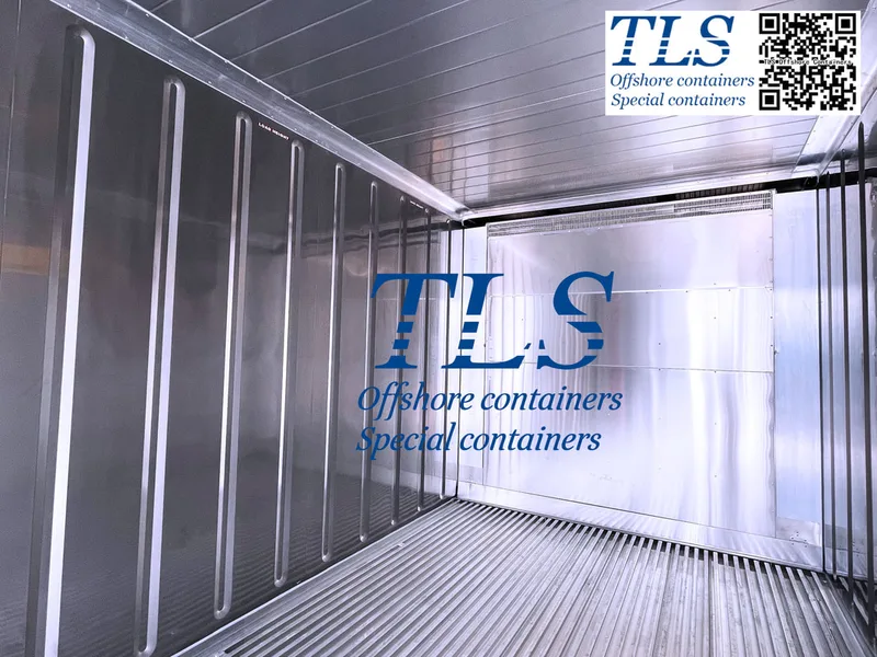
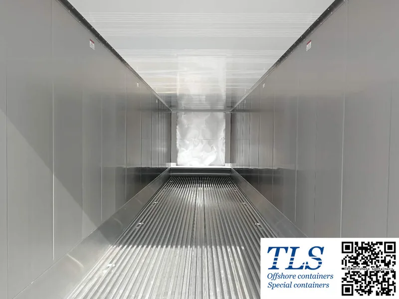
- Maintaining Low Temperatures The reefer’s floor is designed with T-shaped grooves to allow cold air to circulate evenly and maintain stable temperatures. For better cooling efficiency, the interior walls, ceiling, and floor of the container are insulated. However, reefers cannot actively lower the temperature of goods; therefore, cargo must be pre-cooled to the target temperature before loading.
- Power Supply The refrigeration unit is powered either by the ship's electricity or a backup generator, the latter being particularly suitable for highly temperature-sensitive goods.
- Ventilation System The built-in ventilation system removes heat, moisture, and carbon dioxide released by items such as fruits and vegetables, preventing spoilage and quality degradation.
- Humidity Control Reefers are equipped with dehumidification features to adjust humidity to optimal levels, avoiding damage caused by excessive moisture or dryness.
- Drainage System Integrated drainage pipes ensure timely removal of accumulated water, preventing water damage to the cargo.
How to Properly Stow Cargo
Proper stowage of goods is crucial for the effective operation of a reefer:
- Ensure Air Circulation: Avoid over-packing cargo to prevent obstructing airflow.
- Stow According to Cargo Type: For example, fresh meat should be spaced appropriately to allow heat and gas to escape.
- Pre-Cool Cargo: Ensure goods are pre-cooled to the target temperature before loading.
Conclusion
Container refrigerators provide a reliable solution for temperature-controlled transportation, suitable for a variety of goods ranging from frozen foods to fresh produce. Understanding their working principles and proper operation can significantly improve logistics efficiency and maintain cargo quality.
TLS Offshore Containers / TLS Special Containers is a global supplier of standard and customised containerised solutions.
Wherever you are in the world TLS can help you, please contact us.
Any more information regarding Offshore Reefer container, ISO reefer container, please download TLS offshore reefer containers brochure for your reference
Keywords: #TLS container refrigerators,#Reefer containers,#Refrigerated container dimensions,#Temperature-controlled shipping,#Perishable goods transportation,#Refrigeration systems,#Cold storage logistics,#ISO container specifications,#Container ventilation system,#Container humidity control,#Cargo pre-cooling,#Reefer power supply,#T-shaped grooves,#Drainage system in containers,#Food and beverage shipping,#Frozen goods logistics,#Standard reefer sizes,#20-foot refrigerated container,#40-foot reefer container
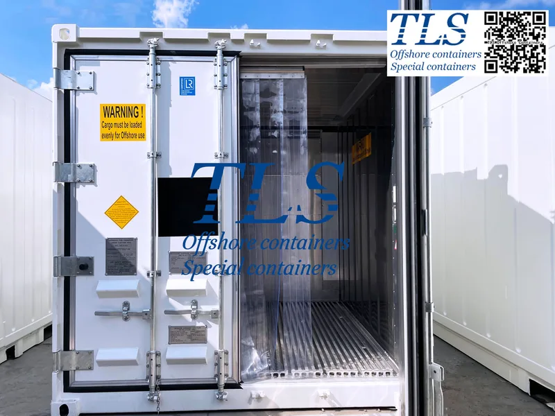
Written by Snowy
- Published on
Battery Energy Storage Systems (BESS) have become a cornerstone of modern energy infrastructure. They enable the seamless integration of renewable energy sources, enhance grid stability, and provide reliable backup power. However, to fully leverage their potential, careful attention must be given to the charging and discharging processes, as these are critical for ensuring safety, optimizing performance, and extending the lifespan of the batteries. This detailed guide outlines the key practices operators must follow to achieve these objectives.
Charging a BESS involves converting electrical energy into chemical energy, stored within the battery for future use. This process, while seemingly straightforward, requires strict adherence to several parameters to ensure safety and longevity. Voltage and current limits are among the most crucial considerations. Every battery has specific voltage and current ratings, defined by the manufacturer. Charging beyond these limits can result in overheating, cell damage, or even catastrophic failure. Operators must monitor and regulate the charging process to stay within these boundaries.
Another important parameter is the state of charge (SOC), which represents the battery’s current energy level as a percentage of its total capacity. Overcharging a battery, or charging it beyond its recommended SOC limit, can lead to reduced efficiency, shorter lifespan, and safety risks. Most modern BESS are equipped with Battery Management Systems (BMS) that automatically manage SOC levels, but operators should still remain vigilant.
Temperature management is another critical aspect of charging. Batteries generate heat during the charging process, and excessive temperatures can accelerate chemical reactions that degrade the battery over time. Ideally, the battery should operate within a temperature range of 15°C to 30°C. Cooling systems, thermal sensors, and proper ventilation are necessary to maintain this range and prevent thermal runaway, a dangerous condition where heat buildup triggers uncontrollable chemical reactions.
Cell balancing is essential for maintaining the health of the battery pack. In a BESS, multiple cells are connected in series or parallel to achieve the desired voltage and capacity. However, not all cells charge at the same rate. Over time, this can result in some cells becoming overcharged while others are undercharged. A BMS ensures balanced charging across all cells, which is vital for preventing uneven wear and ensuring consistent performance.
Environmental factors also play a significant role in the charging process. High humidity, extreme heat, or exposure to dust and debris can affect the battery’s performance and safety. Operators should maintain a clean and controlled environment to minimize these risks. For outdoor installations, protective enclosures and climate control systems are recommended.
Discharging a BESS, where stored chemical energy is converted back into electrical energy for use, also requires careful attention. One of the most critical parameters during discharging is the depth of discharge (DOD). DOD refers to the percentage of the battery’s capacity that has been used. For instance, if a battery is discharged to 40% of its capacity, the DOD is 60%. Exceeding the manufacturer-recommended DOD can significantly reduce the battery’s lifespan and efficiency. Operators must monitor and regulate discharges to avoid over-depleting the battery.
Load management is equally important during discharging. If the connected load demands more power than the battery can safely supply, it can strain the system, leading to overheating or damage. Operators should ensure that the load remains within the battery’s rated output capacity. Additionally, voltage monitoring is crucial to prevent deep discharge, which can occur when the battery’s voltage drops below its minimum threshold. Deep discharge can cause permanent damage to the cells, reducing their ability to hold a charge.
Temperature management is just as critical during discharging as it is during charging. Excessive heat can accelerate the degradation of battery materials, while extremely low temperatures can reduce the battery’s ability to deliver power efficiently. Operators should use thermal management systems to maintain the battery within its optimal operating temperature range.
Safety is paramount when operating a BESS, and a well-functioning Battery Management System (BMS) is key to achieving it. The BMS continuously monitors and controls critical parameters, such as SOC, DOD, voltage, and temperature, to ensure the system operates safely and efficiently. In addition to automation, the BMS provides alerts and diagnostic information to operators, enabling them to respond promptly to potential issues.
Fire and thermal safety systems are also essential. Although rare, conditions such as thermal runaway or electrical faults can pose significant risks. Fire suppression systems, thermal barriers, and emergency shutdown protocols should be in place to mitigate these hazards. Operators must also be trained to handle emergencies, including evacuation procedures and first aid for electrical or chemical injuries.
Regular maintenance and inspections are critical for ensuring the long-term reliability of a BESS. Operators should perform periodic checks to identify signs of wear, corrosion, or physical damage to the battery, connectors, and other components. Keeping the BMS firmware updated is essential for maintaining compatibility with new safety standards and performance enhancements. Additionally, inspecting and securing electrical connections can prevent energy losses or faults caused by loose or corroded contacts.
Environmental conditions can greatly influence the performance and longevity of a BESS. Extreme temperatures, high humidity, and exposure to dust or corrosive substances can degrade the battery over time. Operators should maintain a clean, well-ventilated environment to protect the system. For outdoor installations, weather-resistant enclosures and climate control systems can help mitigate environmental risks.
When integrating a BESS into the grid or using it for commercial and industrial applications, operational considerations such as demand response and frequency regulation must also be managed effectively. Aligning the charging and discharging schedules with grid demands can improve energy efficiency and maximize the economic benefits of the system.
In conclusion, the proper operation of a Battery Energy Storage System requires careful attention to detail during both charging and discharging processes. By monitoring critical parameters such as voltage, current, SOC, DOD, and temperature, operators can ensure the system operates safely and efficiently. Regular maintenance, environmental control, and adherence to manufacturer guidelines are essential for optimizing performance and extending the lifespan of the battery. A well-maintained BESS not only enhances energy reliability and sustainability but also provides a significant return on investment, making it an invaluable asset in the modern energy landscape.